Supercharge Your Innovation With Domain-Expert AI Agents!

A trash rack experimental platform based on the formation of a free liquid surface in a closed water tank with a high water level in a short distance

A technology of closed water tank and high-level water tank, which is applied in the field of pump station engineering, can solve the problems of increasing unnecessary expenditure, difficulty in forming free liquid surface, water spilling, etc., and achieves simple and easy installation process, reduced renovation costs, and reduced workload. Effect

Active Publication Date: 2022-04-15
YANGZHOU UNIV
View PDF10 Cites 0 Cited by
  • Summary
  • Abstract
  • Description
  • Claims
  • Application Information

AI Technical Summary

Problems solved by technology

However, the study of the trash rack needs to form a free liquid surface in front of the trash rack. For the scientificity of the experiment and the universality of the verification experiment results, the experimental flow channel of the trash rack needs to be open or semi-open. Type, often because the water flow in the closed circulation pipeline is too fast, it is difficult to form a free liquid surface, and the simple control of the water volume in the inlet pool cannot meet the operation requirements of the laboratory circulating water pump. In order to obtain the free liquid surface, a trash rack is added The length of the experimental flow channel will occupy too much experimental space and increase a lot of unnecessary expenses
When the experimental flow channel of the trash rack is made open or semi-open in order to release the waste, water will often be spilled from the closed circulation device, which will pollute the laboratory environment, and even lead to safety accidents in serious cases. occur

Method used


Image

  • A trash rack experimental platform based on the formation of a free liquid surface in a closed water tank with a high water level in a short distance
  • A trash rack experimental platform based on the formation of a free liquid surface in a closed water tank with a high water level in a short distance
  • A trash rack experimental platform based on the formation of a free liquid surface in a closed water tank with a high water level in a short distance

Examples


Embodiment Construction

[0033] Below in conjunction with accompanying drawing and description of drawings, the present invention will be further described:

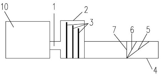
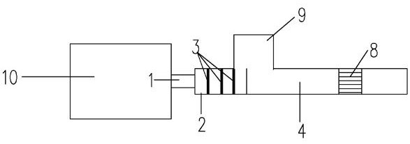
[0034] Based on the trash rack test bench that forms a free liquid surface in the close range of the high water level closed water tank, it consists of the water inlet pipe 1, the closed transparent diversion high level water tank 2, the diverter plate 3, the transparent main body experimental flow channel water tank 4, and simulates long-distance irregularities The dirt movement water tank 9, the trash rack 8 and the trash rack 30° draw-in groove 5, the trash rack 60° draw-in slot 6, and the trash rack 90° draw-in slot 7 form. The trash rack 8 and the trash rack 30° slot 5, the trash rack 60 ° slot 6, and the trash rack 90 ° slot 7 are set and installed in the transparent main body experimental flow channel water tank 4, and the transparent main body experimental flow channel water tank 4 It is mainly made of transparent plexiglass, and its mai...


PUM


Abstract

The invention relates to a trash rack test bench based on a high-water-level airtight water tank forming a free liquid surface in a short distance, which is used to solve the premise that the water pump can run more stably in the experiment due to the narrow space of the existing water pump laboratory equipment Under the current situation, it is difficult to form a free liquid surface in the experimental flow channel. Compared with the previous laboratory, in order to obtain a relatively stable free liquid surface, it needs to occupy too much experimental space, whether it is saving the test site or saving funds. The present invention has certain remarkable advantages. The installation process of the invention is simple and easy to operate, has high reliability, and reduces the workload of the installation workers of the experimental equipment to a certain extent. At the same time, the free liquid surface flow state obtained by the present invention is stable, and is also applicable to other experiments that need to obtain a free liquid surface.

Description

technical field [0001] The invention relates to a trash rack test bench based on the formation of a free liquid surface in a closed water tank with a high water level in a short distance, especially for a test bench with a small space or a high water level inlet tank where it is difficult to form a free liquid surface, and belongs to the technical field of pump station engineering . Background technique [0002] The trash rack has always been in an important position during the operation of the pump station. The quality of its trash rack performance will have a certain impact on the safety and stability of the pump during operation. In addition, during the use of the trash rack, the trash rack The volume and amount of dirt blocked on the trash rack will increase with the increase of use time. When it reaches a critical state, it will inevitably affect the water head before the grid and the water head behind the grid, so more and more Experts and scholars have conducted rese...

Claims


Application Information

Patent Timeline
Patent Type & Authority Patents(China)
IPC IPC(8): G09B25/00
CPCG09B25/00
Inventor 杨帆蒋东进李超汤方平周济人王银
Owner YANGZHOU UNIV
Features
  • R&D
  • Intellectual Property
  • Life Sciences
  • Materials
  • Tech Scout
  • Unparalleled Data Quality
  • Higher Quality Content
  • 60% Fewer Hallucinations
Learn More