
Miniaturized high-power isolated synthetic network device and implementation method

A technology of a network device and an implementation method, applied in the field of communication, can solve the problems of unsatisfactory amplitude and phase consistency of multiple branches, failure to consider isolation, and large inter-stage influence, and achieve good performance characteristics, compact structure, and withstand power. big effect

Inactive Publication Date: 2020-12-25
SICHUAN SIAIPU ELECTRONICS TECH CO LTD
View PDF5 Cites 1 Cited by
  • Summary
  • Abstract
  • Description
  • Claims
  • Application Information

AI Technical Summary

Problems solved by technology

The conventional T-junction is a three-port network, and there is no isolation between stages. When performing power synthesis, the inter-stage influence is greater; the current four-port synthesis network structure and implementation methods usually include E-arm, H-arm, branch waveguide and matching structure, etc., the structure is complex, the amplitude-phase consistency of the multi-branch is not ideal, and the isolation is not considered

Method used


Image

  • Miniaturized high-power isolated synthetic network device and implementation method
  • Miniaturized high-power isolated synthetic network device and implementation method
  • Miniaturized high-power isolated synthetic network device and implementation method

Examples


Embodiment 1

[0054] A method for realizing a miniaturized high-power isolated synthesis network, including steps:

[0055] Step S1: providing a lower chamber 1 and an upper chamber 2;

[0056] Step S2: Carry out milling on the opposite sides of the lower cavity 1 and the upper cavity 2, including:

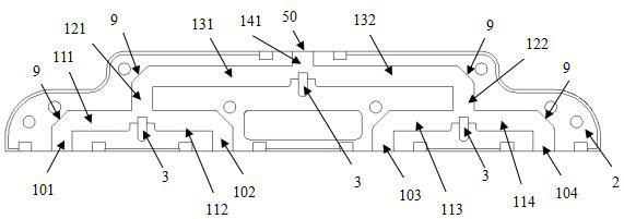
[0057] The corresponding positions on the opposite side are all processed: No. 101 of the first vertical channel I, No. 102 of the first vertical channel II, No. 103 of the first vertical channel III, No. 104 of the first vertical channel IV, and No. 111 of the first horizontal channel , No. 112 of the first horizontal channel II, No. 113 of the first horizontal channel III, No. 114 of the first horizontal channel IV, No. 121 of the second vertical channel I, No. 122 of the second vertical channel II, No. 131 of the second horizontal channel I, No. Second horizontal channel II No. 132, third vertical channel 141;

[0058] The ends of the first vertical channel No. I 101, the first vertical ch...

Embodiment 2

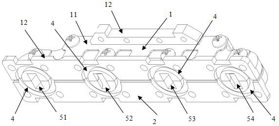
[0072] Such as Figure 1~4 As shown, this example provides a miniaturized high-power isolated composite network device, including: a cavity, and the composite network device is formed in the cavity.

[0073] The cavity body includes a lower cavity 1 and an upper cavity 2 that cooperate with each other. Specifically, the synthetic network device is formed on the mutual mating surface of the lower cavity 1 and the upper cavity 2, and the lower cavity 1 and the upper cavity 2 are locked by fasteners after being matched.

[0074] The miniaturized high-power isolated synthetic network device of this example includes:

[0075] E-arm branch waveguide port I No. 51, E-arm branch waveguide port II No. 52, E-arm branch waveguide port III No. 53, and E-arm branch waveguide port IV No. 54 arranged at equal intervals along a straight line;

[0076] The first vertical channel I No. 101, the first No. 102 of vertical channel II, No. 103 of first vertical channel III, No. 104 of first verti...


PUM


Abstract

The invention discloses a miniaturized high-power isolated synthetic network device and an implementation method. The method comprises the following steps: providing a lower cavity and an upper cavity; milling the opposite surfaces of the lower cavity and the upper cavity to form first vertical channel I-IV, first horizontal channel I-IV, a second vertical channel I, a second vertical channel II,a second horizontal channel I, a second horizontal channel II and a third vertical channel on the opposite surfaces, and arranging an E-arm spacer structure to form E-arm branch waveguide ports I-IV on one side of the lower cavity and the upper cavity in the length direction and an E-arm waveguide port on the other side; arranging the E-arm branch waveguide ports at equal intervals along a straight line; and assembling the lower cavity and the upper cavity to obtain the miniaturized high-power isolated synthetic network. The cavity is formed through one-time milling, network synthesis of fourports in the same plane is achieved through the channels, the E-arm spacer structures, the microstrip probes, the load resistors and the like, consistency of amplitude and phase of multiple branches and good isolation are guaranteed, the size is small, the frequency band is wide, and insertion loss is low.

Description

technical field [0001] The invention belongs to the communication field and relates to waveguide synthesis / microwave power division technology, in particular to a miniaturized high-power isolation synthesis network device and a realization method. Background technique [0002] Waveguide synthesis is used to combine multiple channels of power to obtain greater power. The performance of the composite network, such as insertion loss, isolation, phase balance and amplitude balance, will have a greater impact on the performance of the entire system. The conventional T-junction is a three-port network, and there is no isolation between stages. When performing power synthesis, the inter-stage influence is greater; the current four-port synthesis network structure and implementation methods usually include E-arm, H-arm, branch waveguide and matching Structure and other ways to achieve, the structure is complex, the phase consistency of multi-branch is not ideal, and does not take i...

Claims


Application Information

Patent Timeline
Patent Type & Authority Applications(China)
IPC IPC(8): H01P11/00H01P1/213
CPCH01P1/213H01P11/00
Inventor 商桂川宋垚
Owner SICHUAN SIAIPU ELECTRONICS TECH CO LTD
Learn More