Continuous heating furnace for oil pipe surface treatment

A surface treatment, continuous technology, applied in the direction of pretreatment surface, surface coating liquid device, liquid injection device, etc., can solve the problems of inconvenient use, poor treatment effect, etc., to achieve convenient use, good effect, simple and convenient The effect of using the effect

Active Publication Date: 2020-12-29
DAQING CITY HUAYU PETROLEUM MASCH MFG CO LTD
View PDF4 Cites 1 Cited by
  • Summary
  • Abstract
  • Description
  • Claims
  • Application Information

AI Technical Summary

Problems solved by technology

[0003] When oil is extracted, it is often necessary to use corresponding pipelines for oil transportation. An oil field area often needs to be used for many years. At this time, the buried oil pipes need to be treated in a specific way to prevent them from being affected by corrosion. The existing technology is to repair the oil pipes. The surface is sprayed with anti-corrosion paint to ensure its long service life. The purpose is often to divide the treatment of the oil pipe surface into two parts: spraying paint and heating. In the past, it was a multi-equipment cooperation work. On the one hand, it is inconvenient to use, and at the same time, the treatment effect is relatively poor.

Method used


Image

  • Continuous heating furnace for oil pipe surface treatment
  • Continuous heating furnace for oil pipe surface treatment
  • Continuous heating furnace for oil pipe surface treatment

Examples


Embodiment Construction

[0025] The following will clearly and completely describe the technical solutions in the embodiments of the present invention with reference to the accompanying drawings in the embodiments of the present invention. Obviously, the described embodiments are only some, not all, embodiments of the present invention. Based on the embodiments of the present invention, all other embodiments obtained by persons of ordinary skill in the art without making creative efforts belong to the protection scope of the present invention.

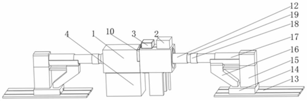
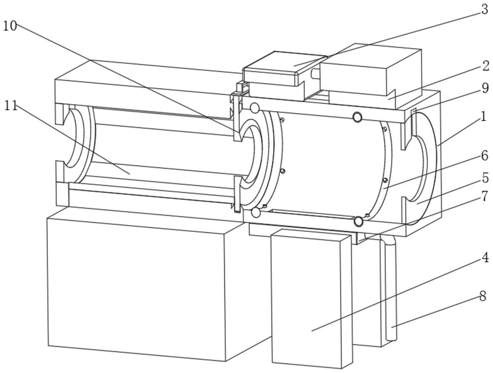
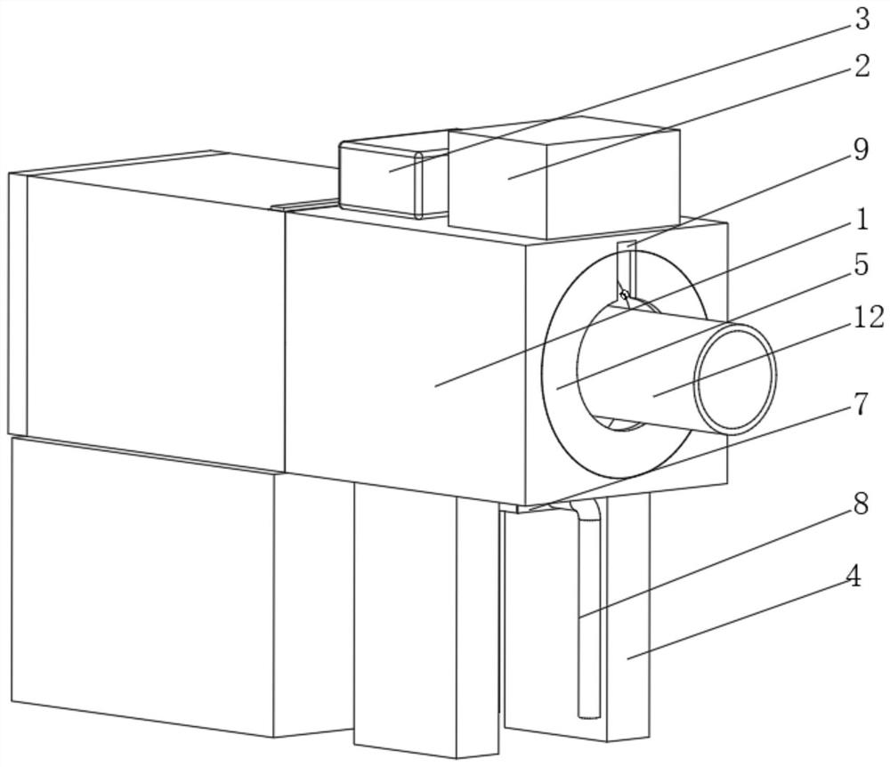
[0026] see Figure 1-7 , a continuous heating furnace for oil pipe surface treatment, comprising a processor 1, a material storage tank 2 is fixedly installed on the right end of the top of the processor 1, a high-pressure air pump 3 is fixedly installed on the left side of the material storage tank 2, and the bottom of the processor 1 The support base 4 is fixedly installed, and the middle part of both sides of the processor 1 is fixedly installed with a prot...


PUM


Abstract

The invention relates to the technical field of petroleum pipelines, and discloses a continuous heating furnace for oil pipe surface treatment. The continuous heating furnace comprises a processor, wherein a storage barrel is fixedly mounted at the right end of the top of the processor; a high-pressure air pump is fixedly mounted on the left side of the storage barrel; a supporting base is fixedlymounted at the bottom of the processor; protective covers are fixedly mounted in the middles of the two sides of the processor; and two sprayers are fixedly mounted at the right end of the interior of the processor. According to the continuous heating furnace for oil pipe surface treatment, the processor, spraying pipes, a heating plate and the like are arranged, so that the purposes of convenient use and good effect are achieved; hydraulic rods at the two ends are used for controlling threaded pipes to fix the position of a large oil pipe, then the hydraulic rods start to extend and retract,that is to say, the oil pipe slowly moves in the processor, the sprayers are arranged in the mode, the high-pressure air pump can be used for quickly realizing the spraying work of the sprayers, andannular material pipes and material spraying heads are uniformly distributed on the periphery of the oil pipe in an annular shape.

Description

technical field [0001] The invention relates to the technical field of petroleum pipelines, in particular to a continuous heating furnace for oil pipeline surface treatment. Background technique [0002] Petroleum, one of the main objects of geological exploration, is a viscous, dark brown liquid known as "industrial blood". There are oil reserves in some areas of the upper crust, and the main components are various alkanes, cycloalkanes, and aromatic hydrocarbons The oil-forming mechanism of petroleum has two theories of biosedimentary oil and petrochemical oil. The former is more widely accepted. It is believed that oil is formed by organisms in ancient oceans or lakes after a long evolution. It belongs to biosedimentary oil and is non-renewable. The latter believes that petroleum is produced by the carbon in the earth's crust itself, has nothing to do with biology, and is renewable. Petroleum is mainly used as fuel oil and gasoline, and is also a raw material for many che...

Claims


Application Information

Patent Timeline
Patent Type & Authority Applications(China)
IPC IPC(8): B05B16/20B05D3/02B05B13/02B05B9/04B05B12/12B05B14/00B05B15/50
CPCB05B9/0409B05B9/0423B05B12/122B05B13/0207B05B13/0278B05D3/0272B05B14/00B05B15/50B05B16/20
Inventor 席赫
Owner DAQING CITY HUAYU PETROLEUM MASCH MFG CO LTD
Why Eureka
Try Eureka