Electronic component conveying device
A technology of electronic components and transmission devices, which is applied in the direction of conveyors, conveyor objects, transportation and packaging, etc., can solve the problems of excessive force, waste of manpower, damage to electronic components, etc., and achieve the effect of soft turning, convenient and efficient
- Summary
- Abstract
- Description
- Claims
- Application Information
AI Technical Summary
Problems solved by technology
Method used
Image

Examples
Embodiment Construction
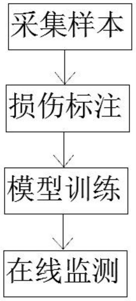
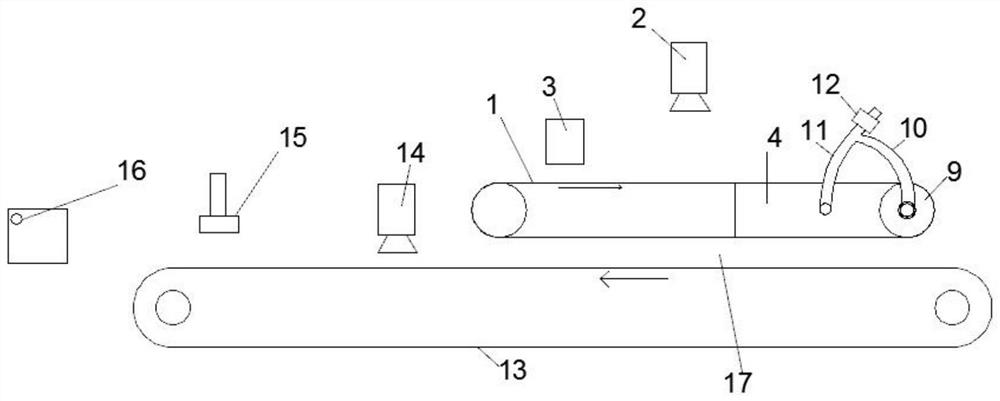
[0016] like figure 1 A method for inspecting electronic components based on machine vision includes the following steps: Step 1. Collect image samples of damage images on the surface of electronic components and image samples without damage to electronic components, and simultaneously collect ultrasonic waves corresponding to the image samples of damage on the surface of electronic components. Flaw detection signals and ultrasonic flaw detection signals corresponding to image samples without damage to electronic components;
[0017] Step 2, manually marking the damage type of the damage image on the surface of the electronic component, and obtaining a sample of the damage image on the surface of the electronic component after marking;
[0018] Step 3. Partially marked damage image samples on the surface of electronic components, image samples without damage to electronic components, and corresponding ultrasonic flaw detection signals are respectively used as positive sample se...
PUM
 Abstract
Description
Claims
Application Information
PatSnap Eureka turns technology decisions into work you can execute. Powered by our Innovation Knowledge Graph, it runs expert workflows across engineering, life sciences, materials and intellectual property. Get your review-ready output in minutes.


