Ship external-hanging propelling device using podded electric propeller
A propulsion device and propeller technology, which is applied in ship propulsion, propulsion device engine, propulsion components, etc., can solve the problem of fuel-powered ships polluting electric ships, etc., and achieves solutions to battery life problems, zero-emission and noise-free work, and avoiding force tests. Effect
- Summary
- Abstract
- Description
- Claims
- Application Information
AI Technical Summary
Problems solved by technology
Method used
Image


Examples
Embodiment 1
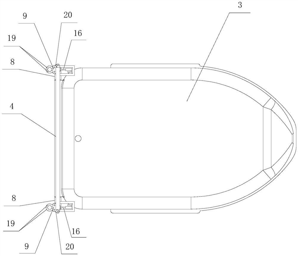
[0063]Example 1: CombinationFigure 1~Figure 8 Shown here is a specific implementation of a ship's external propulsion device using a pod-type electric propeller provided by the present invention. The ship 1 used for propulsion is a common diesel cargo ship. We will describe it in detail below:
[0064]First combinefigure 1 ,figure 2 ,image 3 withFigure 6 As shown, the ship’s external-mounted electric propulsion device using the pod-type electric propeller is composed of a stern connection frame pre-welded to the stern of the ship 1, a navigation floating body 3, a navigation floating body connection frame 4, and a crane installed underneath the navigation floating body 3. Cabin-type electric propeller 5, a driver (not shown in the figure) that is arranged in the navigation floating body 3 to drive the operation of the pod-type electric propeller 5, a battery 7, which is electrically connected to the driver and the pod-type electric propeller 5, and a battery 7 connected to the battery ...
Embodiment 2
[0073]Embodiment 2: The overall structure of this embodiment is the same as that of Embodiment 1. The only difference is the detachable connecting mechanism connecting the stern connecting frame 2 and the sailing floating body connecting frame 4.
[0074]The detachable connecting mechanism in this embodiment also consists of two symmetrical connecting unit mechanisms connecting the stern connecting frame 2 and the sailing floating body connecting frame 4, and the two connecting unit mechanisms are of equal height in the width direction of the ship 1. However, each connecting unit mechanism is a manual mechanical locking mechanism, which is specifically composed of a female end connecting mechanism arranged on the stern connecting frame 2 and a male end connecting mechanism arranged on the navigation floating body connecting frame 4 to cooperate with the female end connecting mechanism constitute.
[0075]CombinePicture 9 As shown, the above-mentioned female end connecting mechanism in thi...
Embodiment 3
[0079]Embodiment 3: The overall structure of this embodiment is the same as that of Embodiment 1. The only difference is the detachable connecting mechanism connecting the stern connecting frame 2 and the sailing floating body connecting frame 4.
[0080]CombinePicture 10 As shown, the detachable connection mechanism in this embodiment is also composed of two symmetrical connection unit mechanisms that connect the stern connection frame 2 and the navigation floating body connection frame 4, and the two connection unit mechanisms are in the width direction of the ship 1. Contour. However, each connecting unit mechanism is different from the electromechanical locking mechanism involved in embodiment 1, specifically by the female end connecting mechanism provided on the stern connecting frame 2 and the navigating floating body connecting frame 4 to cooperate with the female end connecting mechanism The male end connecting mechanism constitutes.
[0081]The female end connecting mechanism is ...
PUM
 Abstract
Description
Claims
Application Information
PatSnap Eureka turns technology decisions into work you can execute. Powered by our Innovation Knowledge Graph, it runs expert workflows across engineering, life sciences, materials and intellectual property. Get your review-ready output in minutes.


