Transient starting electromagnetic valve based on remote control and electromagnetic valve starting method

A remote control and solenoid valve technology, which is applied in the field of solenoid valve startup and transient startup solenoid valve, can solve the problems of equipment operation stability, heat generation, sealing, and overall performance.

Pending Publication Date: 2020-12-29
江西省唯欣高科油压科技股份有限公司
View PDF0 Cites 0 Cited by
  • Summary
  • Abstract
  • Description
  • Claims
  • Application Information

AI Technical Summary

Problems solved by technology

[0003] The current electromagnetic reversing valve generates a magnetic field through the internal electromagnet and drives the valve core to move internally. Due to the operating environment of the electromagnetic reversing valve, the electromagnet in the electromagnetic reversing valve needs to drive the valve core frequently and repeatedly during use. Moveme

Method used


Image

  • Transient starting electromagnetic valve based on remote control and electromagnetic valve starting method
  • Transient starting electromagnetic valve based on remote control and electromagnetic valve starting method
  • Transient starting electromagnetic valve based on remote control and electromagnetic valve starting method

Examples


Embodiment 1

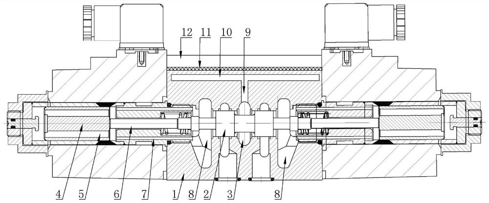
[0025] Embodiment 1: A transient start solenoid valve based on remote control, see Figure 1 to Figure 3 .

[0026] It includes a valve body 1, an electromagnet 13 located on the left and right sides of the valve body 1, a valve core 2 located in the valve body 1, and an armature 4 respectively located in the two electromagnets 13. A guide body 7 is provided in the channel, and a guide hole is provided in the guide body. The front end of the valve core 2 is located in the guide hole and is supported by the guide hole. A push rod 6 is also provided in the guide hole. One end of the push rod 6 is against the end of the valve core 2, and the other end of the push rod 6 is in contact with the end of the armature. The two electromagnets 13 are respectively provided with coils, and the valve body is provided with There are an oil inlet 2 and an oil outlet 8, and the oil outlet 8 is located on the left and right sides of the valve body.

[0027] The above-mentioned structure is the...

Embodiment 2

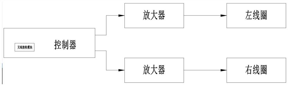
[0035] Embodiment 2, a method for starting a solenoid valve, see image 3 , this method is applied to the electromagnetic valve described in embodiment 1, and it comprises the steps:

[0036] (1) The trigger signal is transmitted to the controller in the form of wireless or wired, and the controller starts the amplifier to increase the starting current;

[0037] (2) The amplifier sends instantaneous high current to the coil of the solenoid valve to start the armature action in an instantaneous and high current manner and drive the valve core to move.

[0038] To sum up, this design starts the movement of the spool transiently. Compared with the smooth movement of the existing spool, the movement time of the spool in this design is greatly reduced. Through this transient start method, the movement of the spool can be greatly saved. Time, reduce the action time of the coil and the electromagnet, and reduce the heat energy generated when the spool is reversing during frequent ac...


PUM


Abstract

The invention discloses a transient starting electromagnetic valve based on remote control and an electromagnetic valve starting method. According to the transient starting electromagnetic valve basedon remote control and the electromagnetic valve starting method, the structural design is novel, and reduction of the heat productivity of the electromagnetic valve is facilitated. The transient starting electromagnetic valve based on remote control comprises a valve body, electromagnets located on the left side and the right side of the valve body and a controller, the controller is connected with two amplifiers, the output ends of the two amplifiers are connected with two coils respectively, the controller receives a trigger signal and controls one amplifier to increase starting current andtransmit high current started instantaneously into the coils, and the coils drive armatures instantaneously to push push rods and a valve element to act. The electromagnetic valve starting method comprises the following steps that 1, the controller starts the amplifiers to increase starting current; and 2, the amplifiers transmit the instantaneous high current to the coils of the electromagneticvalve to instantaneously start the armatures to act.

Description

technical field [0001] The invention relates to a hydraulic electromagnetic reversing valve, in particular to a remote control-based transient start solenoid valve and a method for starting the solenoid valve. Background technique [0002] Electromagnetic reversing valve is an industrial equipment controlled by electromagnetic. It is an automatic basic component used to control fluid. It belongs to actuator. Its application is not limited to hydraulic pressure. It is used in industrial control system to adjust the direction and flow of medium. , speed and other parameters, the electromagnetic reversing valve can cooperate with different circuits to achieve the desired control. [0003] The current electromagnetic reversing valve generates a magnetic field through the internal electromagnet and drives the valve core to move internally. Due to the operating environment of the electromagnetic reversing valve, the electromagnet in the electromagnetic reversing valve needs to dri...

Claims


Application Information

Patent Timeline
IPC IPC(8): F15B13/02F15B21/00F16K31/06F16K49/00
CPCF15B13/021F15B21/00F16K31/0675F16K31/0696F16K49/00
Inventor 欧阳电苟
Owner 江西省唯欣高科油压科技股份有限公司
Why Eureka
Try Eureka