Automatic cut-off pipe control valve for sewage discharging
A pipeline control valve, automatic technology, applied in the direction of sliding valves, indoor sanitary pipeline devices, pipe components, etc., can solve the problems of foreign matter polluting the environment and affecting people's health, and achieve the effect of reducing labor
- Summary
- Abstract
- Description
- Claims
- Application Information
AI Technical Summary
Problems solved by technology
Method used
Image

Examples
Embodiment 1
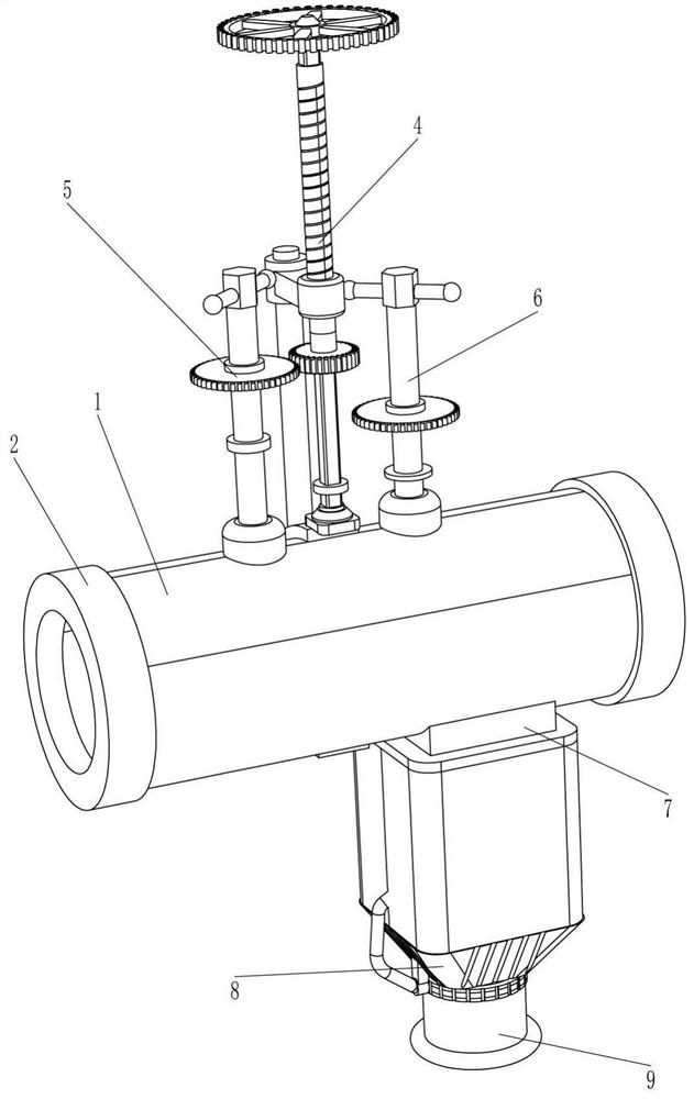
[0068] Such as Figure 1-Figure 2 As shown in the figure, a sewage discharge automatic cut-off pipeline control valve includes a mounting pipe 1, a mounting ring 2, a sealing block 3, a driving mechanism 4, a sealing mechanism 5, a pushing mechanism 6 and a sewage discharge mechanism 7, and the left and right sides of the mounting pipe 1 are Both are connected with installation ring 2, the left and right sides of installation pipe 1 are connected with sealing blocks 3, the upper and rear side of installation pipe 1 is connected with driving mechanism 4, and the upper left side of installation pipe 1 and driving mechanism 4 are connected with sealing block Mechanism 5, a push mechanism 6 is connected between the upper right side of the installation pipe 1 and the drive mechanism 4, and a sewage discharge mechanism 7 is connected between the lower right side of the installation pipe 1 and the push mechanism 6.
[0069]When the water pipe needs to be drained, the equipment should...
Embodiment 2
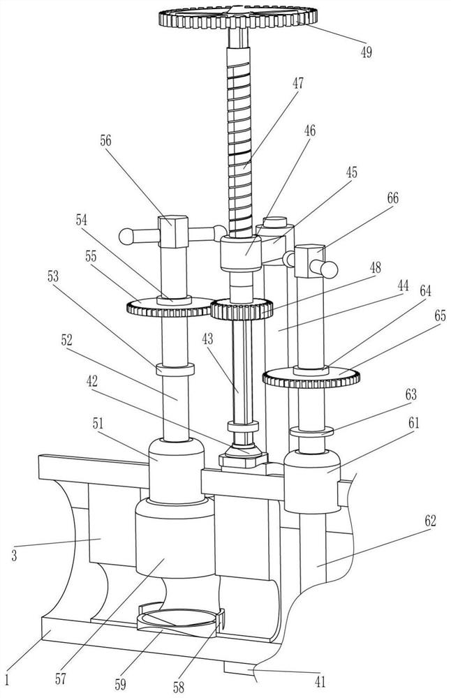
[0071] Such as image 3 As shown, on the basis of Embodiment 1, the driving mechanism 4 includes a fixed ring 41, a shaft sleeve 42, a square rod 43, a vertical rod 44, a fixed frame 45, an internal thread ring 46, a square hole threaded pipe 47, a first Gear 48 and adjusting ring 49, fixed ring 41 is connected to the rear side of the middle part of the installation pipe 1, a shaft sleeve 42 is connected to the top of the fixed ring 41, a square rod 43 is rotatably connected to the shaft sleeve 42, and a vertical rod is connected to the rear side of the fixed ring 41 44, the upper part of the vertical rod 44 is connected with a fixed frame 45, the front side of the fixed frame 45 is connected with an internal thread ring 46, and the internal thread ring 46 is internally threaded and connected with a square hole threaded pipe 47, and the square hole threaded pipe 47 and the square rod 43 slide Connect, square bar 43 tops are connected with adjusting ring 49, square hole threade...
Embodiment 3
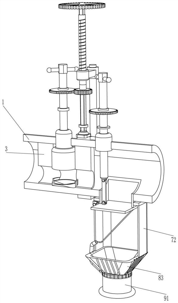
[0076] Such as Figure 3-Figure 5 As shown, on the basis of Embodiment 2, the pushing mechanism 6 includes a second nut 61, a second screw rod 62, a second rubber ring 63, a second fixed connection ring 64, a third gear 65 and a second handle 66 The right side of the upper part of the installation pipe 1 is connected with a second nut 61, the second nut 61 is internally threaded with a second screw 62, the bottom of the second screw 62 is rotationally connected with the sewage mechanism 7, and the middle of the second screw 62 is connected with a second Rubber ring 63, the second screw rod 62 top is connected with the second fixed connection ring 64, the second fixed connection ring 64 is connected with the third gear 65, the third gear 65 meshes with the first gear 48, the second screw rod 62 top is connected with The second turning handle 66.
[0077] When the first gear 48 moves down and meshes with the third gear 65, it drives the third gear 65 to rotate, so that the seco...
PUM
 Abstract
Description
Claims
Application Information
 - R&D Engineer
- R&D Manager
- IP Professional
- Industry Leading Data Capabilities
- Powerful AI technology
- Patent DNA Extraction
Browse by: Latest US Patents, China's latest patents, Technical Efficacy Thesaurus, Application Domain, Technology Topic.
© 2024 PatSnap. All rights reserved.Legal|Privacy policy|Modern Slavery Act Transparency Statement|Sitemap