
Vacuum drying device for pharmacy

A technology of vacuum drying device and drying box, which is applied in the direction of heating device, drying solid material, drying room/container, etc., and can solve the problems of poor vacuum drying effect and so on

Inactive Publication Date: 2020-12-29
ANHUI YONSENT PHARMA
View PDF0 Cites 0 Cited by
  • Summary
  • Abstract
  • Description
  • Claims
  • Application Information

AI Technical Summary

Problems solved by technology

[0004] Based on the technical problem of poor vacuum drying effect on medicines in the prior art, the present invention proposes a vacuum drying device for pharmaceuticals

Method used


Image

  • Vacuum drying device for pharmacy
  • Vacuum drying device for pharmacy
  • Vacuum drying device for pharmacy

Examples


Embodiment 1

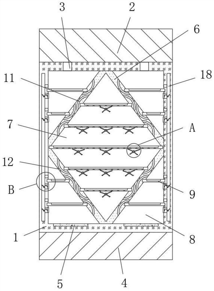
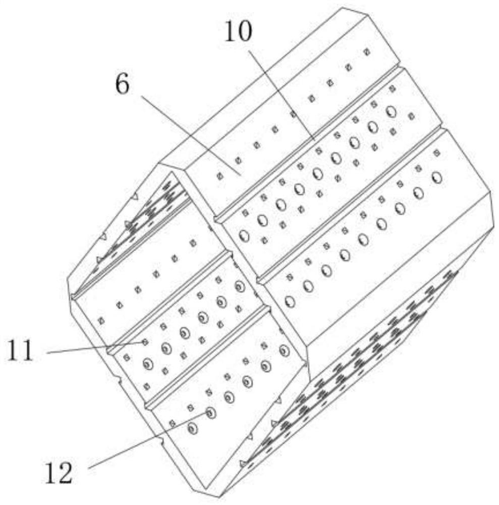
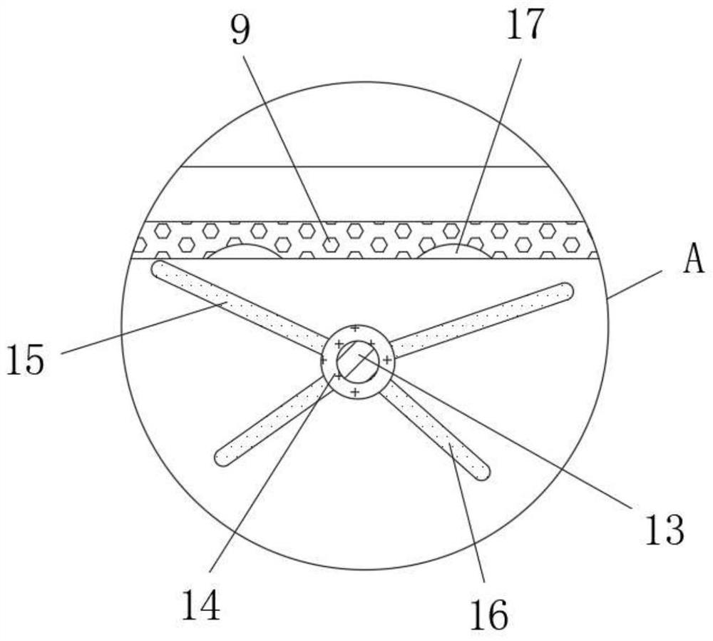
[0026] refer to Figure 1-3 , a vacuum drying device for pharmaceuticals, comprising a drying box 1, a top box 2 and a bottom box 4 are respectively fixed on the top and bottom of the drying box 1, and the bottom of the top box 2 is connected with a vacuum exhaust pipe 3, and the top of the bottom box 4 The heating element 5 is connected, and the inner wall of the drying box 1 is fixed with a fixed frame 6 with a rhombic cross-section, and the middle position of the fixed frame 6 is formed with a placement cavity 7, and the outer wall of the fixed frame 6 and the inner wall of the drying box 1 are formed. A plurality of auxiliary chambers 8, the inner walls of both sides of the placement chamber 7 and the auxiliary chamber 8 are provided with a plurality of chutes 10, and a tray 9 is slidably connected between two adjacent chutes 10, and one end of the drying box 1 is provided with a box Door.

[0027] In the present invention, the position corresponding to the outer wall and...

Embodiment 2

[0031] refer to Figure 1-4 , a kind of vacuum drying device for pharmacy, the inner walls of both sides of the drying box 1 are provided with a flow chamber 18, and the inner wall of the flow chamber 18 close to the fixed frame 6 is provided with a plurality of penetrating limiting grooves 19, the flow chamber 18 is fixed with a spring 21 at the position corresponding to the inner wall of one side away from the fixed frame 6 and the limit groove 19, and one end of the spring 21 is fixed with a deflector 20 with a mesh structure, and the outer wall of the deflector 20 is connected to the limit groove 19. The inner walls are slidingly connected, and the inner walls on both sides of the drying box 1 are located on the top of the tray 9 to open a plurality of air holes 22 , and the air holes 22 communicate with the circulation chamber 18 .

[0032] When in use, along with the airflow movement generated by air extraction and heating, the deflector 20 is reciprocated along the limi...


PUM


Abstract

The invention belongs to the technical field of pharmacy, and particularly relates to a vacuum drying device for pharmacy. The vacuum drying device aims to solve the problem that in the prior art, themedicine vacuum drying effect is poor. According to the scheme, the vacuum drying device comprises a drying box, wherein a top box and a bottom box are fixed to the top and the bottom of the drying box respectively, vacuum exhaust pipes are connected to the bottom of the top box, and heating pieces are connected to the top of the bottom box; and a fixing frame with the section of a rhombus structure is fixed to the inner wall of the drying box, a placement cavity is formed in the middle position of the fixing frame, and a plurality of auxiliary cavities are formed between the outer wall of the fixing frame and the inner wall of the drying box. According to the vacuum drying device for pharmacy, the airflow movement effect is improved through the change of the width in the vertical direction, connecting holes of the rhombus structures of the fixing frame are matched, then airflow around medicine on a supporting plate generates flow speed change and direction change, and the contact effect of the airflow with the medicine is improved through irregular collision, so that the actual vacuum drying completeness and drying efficiency of the medicine are improved.

Description

technical field [0001] The invention relates to the technical field of pharmacy, in particular to a vacuum drying device for pharmacy. Background technique [0002] Pharmaceutical engineering is a processing activity intersecting chemistry, biology, pharmacy (Chinese medicine) and engineering. In the process of pharmaceutical production and processing, it is often necessary to dry the finished drug or the intermediate of the drug. Nowadays, the drug is often dried by vacuum drying. Operation. [0003] The vacuum drying operation of drugs is a drying method in which the material is placed under negative pressure conditions, and the boiling point under the negative pressure state is reached by heating appropriately, or the material is solidified by cooling to dry the material through the melting point. Put the medicine in the tray and place it in the drying chamber, and cooperate with the vacuum equipment to draw negative pressure in the chamber where the medicine is placed t...

Claims


Application Information

Patent Timeline
IPC IPC(8): F26B11/18F26B5/04F26B23/00F26B25/00F26B25/18
CPCF26B5/04F26B11/18F26B23/00F26B25/00F26B25/18
Inventor 夏运喜秦玉华闫明义
Owner ANHUI YONSENT PHARMA
Learn More