Rotor punching sheet, rotor iron core, motor and compressor

A technology of rotor punching and rotor core, which is applied in the field of compressors, can solve the problems that the magnetic isolation bridge of the rotor bears a large force, and the magnetic isolation bridge cannot meet the structural strength requirements of the rotor, etc.

Pending Publication Date: 2020-12-29
ANHUI MEIZHI PRECISION MFG
View PDF0 Cites 0 Cited by
  • Summary
  • Abstract
  • Description
  • Claims
  • Application Information

AI Technical Summary

Problems solved by technology

However, when the motor is operating at high speed, the magnetic isolation bridge of the rotor bears a large force, and the narrow magnetic isolation bridge is difficult to meet the structural strength requirements of the rotor at high speed.

Method used


Image

  • Rotor punching sheet, rotor iron core, motor and compressor
  • Rotor punching sheet, rotor iron core, motor and compressor
  • Rotor punching sheet, rotor iron core, motor and compressor

Examples


Embodiment 1

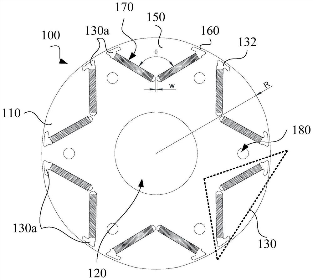
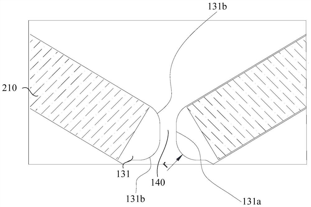
[0066] According to the first aspect of the present invention, such as figure 1 and figure 2 As shown, a rotor punch 100 is provided, which includes a punch body 110 , a shaft hole 120 and a plurality of mounting parts 130 , wherein the shaft hole 120 is disposed on the punch body 110 . A plurality of mounting portions 130 are disposed on the die body 110 around the shaft hole 120 . Each mounting part 130 in the plurality of mounting parts 130 includes two magnet slots 130a, and each magnet slot 130a in the two magnet slots 130a includes a first slot end 131 close to the shaft hole 120, wherein the first slot end 131 includes a straight The groove segment 131a and the arc groove segment 131b connected to the two ends of the straight groove segment 131a.

[0067] The rotor punch 100 provided by the present invention includes a punch body 110 , a shaft hole 120 and a plurality of mounting parts 130 . The shaft hole 120 is opened on the punching body 110, and the punching bod...

Embodiment 2

[0081] On the basis of the foregoing examples, as figure 1 and figure 2 As shown, in this embodiment, a specific description is made for the second slot end 132 of the magnet slot 130a away from the shaft hole 120. Further, the magnet slot 130a includes the second slot end 132 away from the shaft hole 120, and the two first slot ends The distance between 131 is smaller than the distance between the two second groove ends 132, and the second groove ends 132 extend toward the interior of the installation area 150, and the part of the punching between the second groove ends 132 and the outer periphery of the punch body 110 The sheet body 110 constitutes a second magnetic isolation bridge 160 .

[0082] In this embodiment, the magnet slot 130 a further includes a second slot end 132 away from the shaft hole 120 , and the second slot end 132 and the first slot end 131 are opposite ends of the magnet slot 130 a. Since the number of magnet slots 130a is two, the number of second s...

Embodiment 3

[0086] According to a second aspect of the present invention, a rotor core is provided, including the rotor punch 100 provided in any one of the above-mentioned embodiments.

[0087] The rotor core provided by the present invention includes the rotor punch 100 provided by any of the above-mentioned designs, so it has all the beneficial effects of the rotor punch 100 , which will not be repeated here.

[0088] The rotor punch 100 provided by the present invention includes a punch body 110 , a shaft hole 120 and a plurality of mounting parts 130 . The shaft hole 120 is opened on the punching body 110, and the punching body 110 is made of silicon steel. Among them, silicon steel refers to silicon alloy steel with a silicon content of 1.0% to 4.5% and a carbon content of less than 0.08%. Silicon steel has the characteristics of high magnetic permeability, low coercive force, and large resistivity, so the hysteresis loss and eddy current loss are relatively small. The shaft hole ...


PUM

PropertyMeasurementUnit
Widthaaaaaaaaaa

Abstract

The invention provides a rotor punching sheet, a rotor iron core, a motor and a compressor. The rotor punching sheet comprises a punching sheet body, a shaft hole and a plurality of mounting parts, and the shaft hole is formed in the punching sheet body. The plurality of mounting parts are arranged on the punching sheet body around the shaft hole. Each mounting part comprises two magnet grooves, each magnet groove comprises a first groove end close to the shaft hole, and each first groove end comprises a straight groove section and arc groove sections connected to the two ends of the straightgroove section. The first groove end, close to the shaft hole, in each magnet groove comprises the straight groove section and the arc groove sections, on the basis of effectively improving magnetic flux leakage and demagnetization phenomena of the permanent magnets located in the magnet grooves, stress deformation of the rotor punching sheet under the conditions of a high rotating speed and a large torque of the motor can be reduced, the mechanical strength of the rotor punching sheet is improved, motor reliability is enhanced, a problem that the mechanical strength of the rotor punching sheet of the motor is difficult to meet the requirement at a high rotating speed is solved, and a design of the low-magnetic-flux-leakage and high-strength motor is realized.

Description

technical field [0001] The invention relates to the technical field of motor equipment, in particular to a rotor punch, a rotor iron core, a motor and a compressor. Background technique [0002] At present, the rotor composition of the motor includes rotor punching, which is a key component of the rotor, and the design of the rotor punching directly determines the performance of the motor. In order to improve the magnetic steel demagnetization and magnetic leakage phenomenon of the motor, and improve the utilization rate of the magnetic steel. It is often used to reduce the width of the magnetic isolation bridge of the rotor punch. However, when the motor is operating at high speed, the magnetic isolation bridge of the rotor bears a large force, and the narrow magnetic isolation bridge is difficult to meet the structural strength requirements of the rotor at high speed. Therefore, how to increase the structural strength of the rotor on the basis of reducing magnetic flux l...

Claims


Application Information

Patent Timeline
IPC IPC(8): H02K1/27
CPCH02K1/2766H02K2213/03
Inventor 王玉龙毛临书邱小华江波李为谦
Owner ANHUI MEIZHI PRECISION MFG
Why Eureka
Try Eureka