Quasi-zero stiffness vibration isolator with energy recovery function
An energy recovery, quasi-zero stiffness technology, applied in the direction of shock absorber, shock absorber, control mechanical energy, etc., can solve the problem of large lateral space occupation of vibration isolator, inability to apply, etc., to improve the vibration isolation effect and reduce the lateral size. Small, the effect of reducing the natural frequency
- Summary
- Abstract
- Description
- Claims
- Application Information
AI Technical Summary
Problems solved by technology
Method used
Image
Examples
Embodiment 1
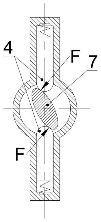
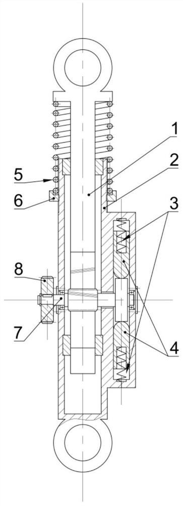
[0028] Such as figure 1 As shown, a quasi-zero stiffness vibration isolator with energy recovery function includes a housing 2, a positive stiffness mechanism, a negative stiffness mechanism, an energy recovery mechanism and an adjustment mechanism; the positive stiffness mechanism includes a rack shaft 1 and a main spring 5; The negative stiffness mechanism includes a gear camshaft 7, a strut 4 and an auxiliary spring 3; the energy recovery mechanism includes a gear pair and a generator 10, and the gear pair is composed of a transmission bull gear 8 and a transmission pinion 9; the adjustment mechanism is an adjustment bolt 6.
[0029] Such as figure 1 As shown in (a), the housing 2 is hollow, and the two ends of the rack shaft 1 are connected inside the housing 2 through sliding bearings. The end of the rack shaft 1 is in contact with the upper end of the main spring 5, and the lower end of the main spring 5 is in contact with the adjustment bolt 6. , the adjusting bolt 6 i...
Embodiment 2
[0043] The difference from Embodiment 1 lies in the installation position of the main spring 5 that provides positive stiffness. In this embodiment, the main spring 5 is installed outside the housing 2, and the corresponding adjustment bolt 6 for adjusting the balance position becomes an adjustment nut. Such as image 3 As shown, the main spring 5 is sleeved on the upper end of the housing 2, the lower end of the main spring 5 is in contact with the adjusting nut sleeved on the housing 2, the upper end of the main spring 5 is in contact with the upper end of the rack shaft 1, and the inner thread of the adjusting nut is in contact with the housing. 2. When the external thread is matched and the adjusting nut is turned, the adjusting nut moves up and down along the central axis of the housing 2. During the above-mentioned movement, the main spring 5 is always in a compressed state; the upper end of the rack shaft 1 is provided with a mounting hole. The end of the housing 2 is a...
PUM
 Abstract
Description
Claims
Application Information
 - R&D
- Intellectual Property
- Life Sciences
- Materials
- Tech Scout
- Unparalleled Data Quality
- Higher Quality Content
- 60% Fewer Hallucinations
Browse by: Latest US Patents, China's latest patents, Technical Efficacy Thesaurus, Application Domain, Technology Topic, Popular Technical Reports.
© 2025 PatSnap. All rights reserved.Legal|Privacy policy|Modern Slavery Act Transparency Statement|Sitemap|About US| Contact US: help@patsnap.com


