
Garbage treatment device for environment-friendly machine

The technology of a garbage disposal device and machinery, which is applied in the directions of garbage drying, dryer, press, etc., can solve the problems affecting the garbage compression effect, etc., and achieve the effect of improving the effect, improving the adequacy, and increasing the compression area.

Inactive Publication Date: 2021-01-01
苏州浔宇新材料科技有限公司
View PDF0 Cites 0 Cited by
  • Summary
  • Abstract
  • Description
  • Claims
  • Application Information

AI Technical Summary

Problems solved by technology

[0003] The existing garbage treatment devices simply compress the garbage, and there are often a large amount of magnetic metal garbage in the garbage. During the compression process, it will affect the compression effect of the garbage. Therefore, it is necessary to design an environmentally friendly mechanical garbage collector. Processing means to solve the above problems

Method used

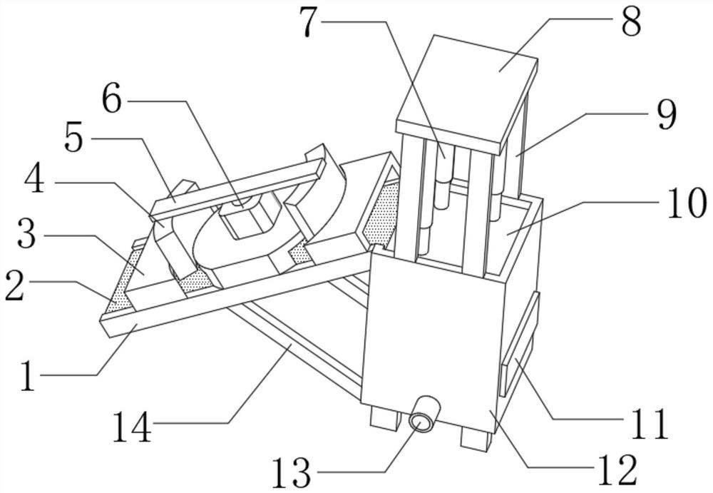

Image

  • Garbage treatment device for environment-friendly machine
  • Garbage treatment device for environment-friendly machine
  • Garbage treatment device for environment-friendly machine

Examples


Embodiment 1

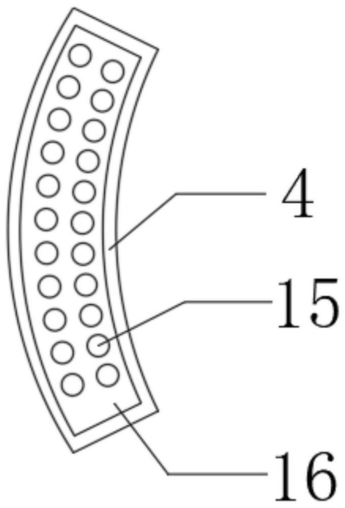
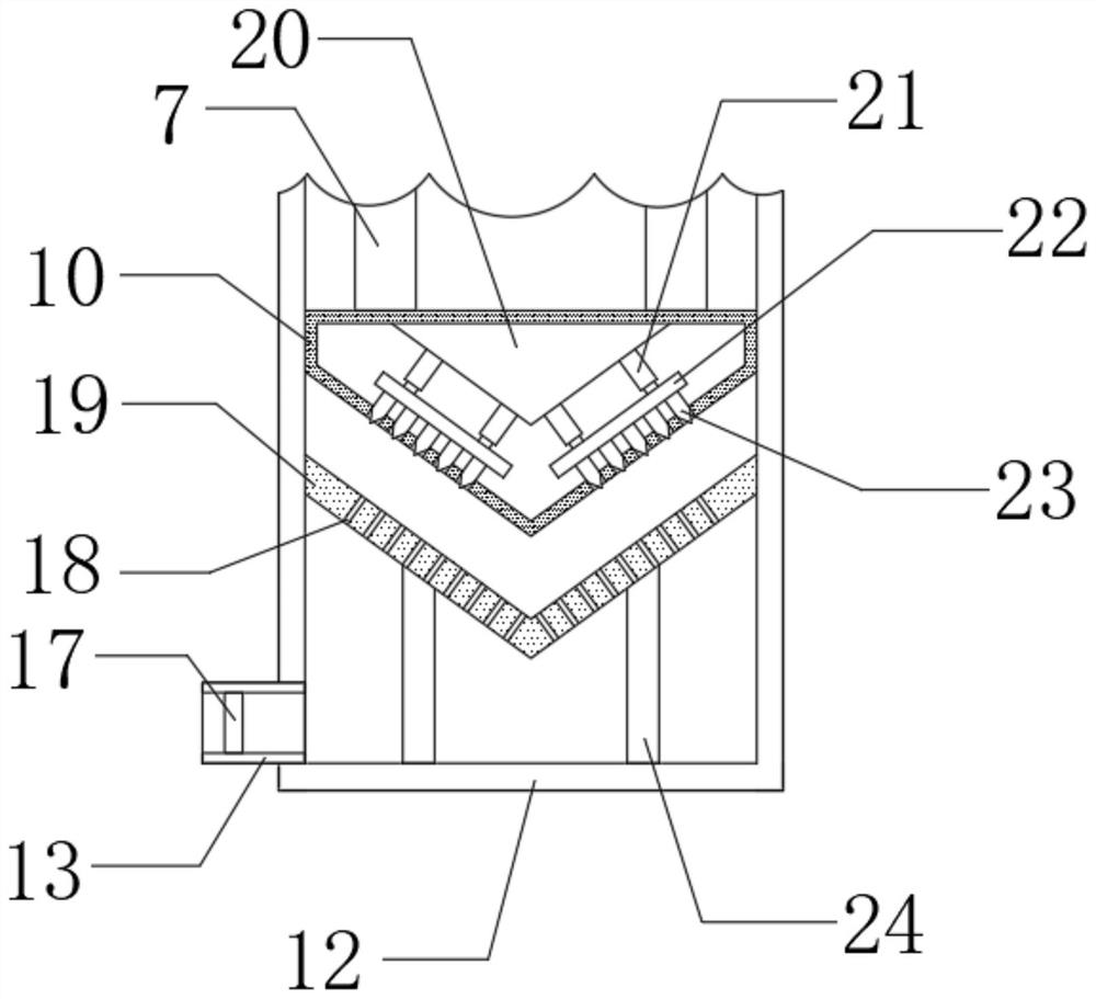
[0031] A garbage disposal device for environmental protection machinery, such as Figure 1-4 As shown, including the storage housing 12, the outer walls at the four corners of the bottom of the storage housing 12 are connected with support legs by bolts, and the outer walls at both ends of the bottom of one side of the storage housing 12 are connected with second support rods 14 by bolts. And the outer walls on one side of the two second support rods 14 are all connected with splints 1 by bolts, and the outer walls on one side of the two splints 1 are respectively connected to the outer walls at both ends of the top of one side of the storage housing 12 by bolts, and the two splints 1 The same conveyor belt 2 is connected by bolts, and the top outer wall of the conveyor belt 2 is connected with a protective shell 3 by bolts, and the top central outer wall of the protective shell 3 is connected with a rotating motor 6 by bolts, and the output shaft of the rotating motor 6 passes...

Embodiment 2

[0041] A garbage disposal device for environmental protection machinery, such as Figure 1-5 As shown, it also includes an air distribution pipe 27 installed on the bottom outer wall of the other end of the material storage housing 12 by bolts, and the outer wall at one end of the air distribution pipe 27 is connected with an exhaust pipe 26 equidistantly inclined by bolts, and the air distribution pipe The outer wall of the other end of 27 is connected with air duct 28 by bolts.

[0042] When this embodiment is in use, a hot air blower is externally connected to the air guide pipe 28, and the hot air is blown to the exhaust pipe 26 by the hot air blower, and then the garbage inside the storage housing 12 is dried by the hot air, which further improves the Garbage collection effect.


PUM


Abstract

The invention discloses a garbage treatment device for an environment-friendly machine, and relates to the technical field of environment-friendly machines. The garbage treatment device aims at solving the problem that an existing garbage treatment device is insufficient in garbage compression. The device specifically comprises a material storage shell, supporting legs are fixedly installed on theouter walls of the four corners of the bottom of the material storage shell, second supporting rods are fixedly installed on the outer walls of the two ends of the bottom of one side of the materialstorage shell, and clamping plates are fixedly installed on the outer walls of one sides of the two second supporting rods. According to the garbage treatment device for the environment-friendly machine, through arranging a second electric extendable rod, a mounting plate and a conical block, in the garbage compression process, the mounting plate and the conical block can be driven by the second electric extendable rod to move, the garbage is punctured by the conical block, and the situation that air II in the garbage is difficult to fully compress is avoided, so that the garbage compression sufficiency is further improved through the arrangement.

Description

technical field [0001] The invention relates to the technical field of environmental protection machinery, in particular to a garbage disposal device for environmental protection machinery. Background technique [0002] Garbage is solid waste generated in human daily life and production. Due to the large amount of discharge, complex and diverse components, and polluting, resourceful and social nature, it needs harmless, resourceful, reduction and socialized treatment. If it is not handled properly, it will pollute the environment, affect environmental sanitation, and waste resources. Garbage disposal is to quickly remove garbage, and conduct harmless treatment, and finally make reasonable use of it. [0003] The existing garbage treatment devices simply compress the garbage, and there are often a large amount of magnetic metal garbage in the garbage. During the compression process, it will affect the compression effect of the garbage. Therefore, it is necessary to design an...

Claims


Application Information

Patent Timeline
IPC IPC(8): B09B3/00B09B5/00B03C1/22B03C1/30B30B9/06B30B15/32F26B21/00
CPCB09B3/00B09B5/00B03C1/22B03C1/30B30B9/062B30B15/32F26B21/004F26B2200/04B09B2101/02B09B3/40
Inventor 刘新
Owner 苏州浔宇新材料科技有限公司
Learn More