Seat type sliding bearing cooling mechanism
A technology of seat type sliding bearing and cooling mechanism, which is applied in the direction of bearing cooling, bearing components, shafts and bearings, etc., can solve the problem of inability to provide reliable oil cooling, reduce weight, avoid flexural deformation, and increase bending resistance. the effect of strength
- Summary
- Abstract
- Description
- Claims
- Application Information
AI Technical Summary
Problems solved by technology
Method used
Image

Examples
Embodiment 1
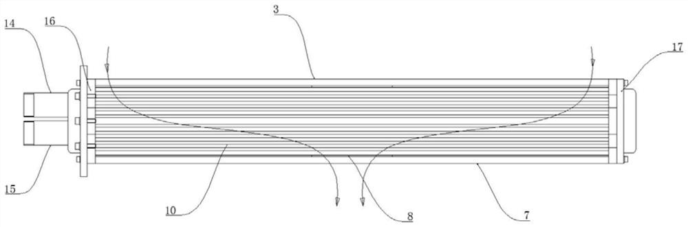
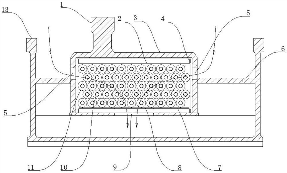
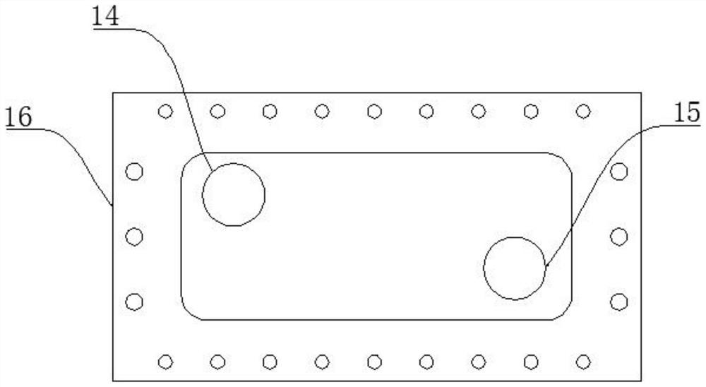
[0023] Embodiment 1, a seat-type sliding bearing cooling mechanism, includes a bearing loading base 13 and a cooler. The bearing loading base 13 is provided with a rectangular loading box 3, and the left side of the loading box 3 is opened, and the cooler is inserted into the Inside the loading box 3. Such as figure 2 As shown: the loading box 3 is located in the middle of the bearing loading seat 13, the front side wall, the rear side wall of the loading box 3 and the inner wall of the bearing loading seat 13 are uniformly formed with partitions 6, and the top of the loading box 3 is integrally formed for supporting Bearing support seat 1. Both the front side wall and the rear side wall of the loading box 3 are provided with an oil inlet 5 , and the oil inlet 5 is located above the dividing plate 6 . combine as figure 1 As shown, the cooler is in the shape of a flat cuboid, and the cooler includes a left end plate 16, a right end plate 17, an upper panel 2 and a lower pan...
Embodiment 2
[0025] Example 2, combined with Figure 5As shown, the two oil inlets 5 on the front side wall and the rear side wall of the loading box 3 in this embodiment are distributed diagonally. In this embodiment, the flow of hot oil enters from two opposite corners on the upper part of the cooler, then flows from the corners to the middle and from top to bottom, and the two oil inlets 5 enter the hot oil from both ends at the same time, so that The hot oil fully flows in the cooler for heat exchange, and the cooling effect on the hot oil is better.
Embodiment 3
[0026] Embodiment 3. In this embodiment, the cooling copper pipe is a U-shaped pipe, the water inlet end of the cooling copper pipe is located at the bottom, and the water outlet end is located at the top. In this way, the cooling water in the cooling copper pipe flows from bottom to top, and forms convection with the hot oil flowing from top to bottom, so that the heat exchange efficiency is higher and the cooling effect on the lubricating oil is better.
PUM
 Abstract
Description
Claims
Application Information
 - R&D
- Intellectual Property
- Life Sciences
- Materials
- Tech Scout
- Unparalleled Data Quality
- Higher Quality Content
- 60% Fewer Hallucinations
Browse by: Latest US Patents, China's latest patents, Technical Efficacy Thesaurus, Application Domain, Technology Topic, Popular Technical Reports.
© 2025 PatSnap. All rights reserved.Legal|Privacy policy|Modern Slavery Act Transparency Statement|Sitemap|About US| Contact US: help@patsnap.com