
Tube plate mounting structure of quick-connection type tubular heat exchanger for chemical engineering

A technology of tube-and-tube heat exchanger and installation structure, which is applied to indirect heat exchangers, heat exchanger types, heat exchanger shells, etc., which can solve the inconvenience of timely detection and replacement of heat exchange tubes, increase the labor intensity of staff, and reduce Equipment repair efficiency and other issues, to achieve the effect of convenient detection and replacement operations, improve repair efficiency, and reduce cooling costs

Active Publication Date: 2021-01-01
惠州忠信化工有限公司
View PDF6 Cites 3 Cited by
  • Summary
  • Abstract
  • Description
  • Claims
  • Application Information

AI Technical Summary

Problems solved by technology

[0003] At present, most of the heat exchange tubes and tube sheets of the common chemical quick-connect tube heat exchangers on the market are connected by welding. There are hundreds of thousands of points, which leads to the fact that once the solder joints of the heat exchange tube and the tube sheet are welded or desoldered during the welding process, it will directly affect the normal use of the equipment. At the same time, the fixed heat exchange tube is very It is not convenient for the staff to detect and replace in time. If the heat exchange tube is damaged during long-term use, the staff needs to spend a lot of time and energy on the replacement operation, which greatly increases the labor intensity of the staff during the maintenance process. Reduce equipment maintenance efficiency

Method used


Image

  • Tube plate mounting structure of quick-connection type tubular heat exchanger for chemical engineering
  • Tube plate mounting structure of quick-connection type tubular heat exchanger for chemical engineering
  • Tube plate mounting structure of quick-connection type tubular heat exchanger for chemical engineering

Examples


Embodiment Construction

[0028] The following examples are for illustrative purposes only and are not intended to limit the scope of the invention.

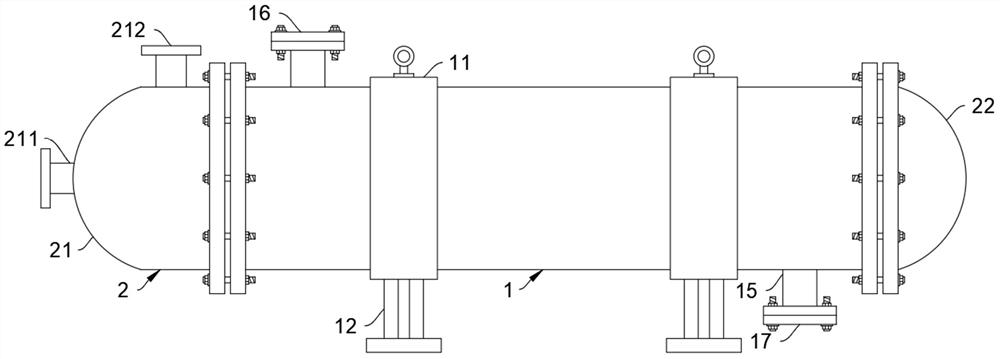
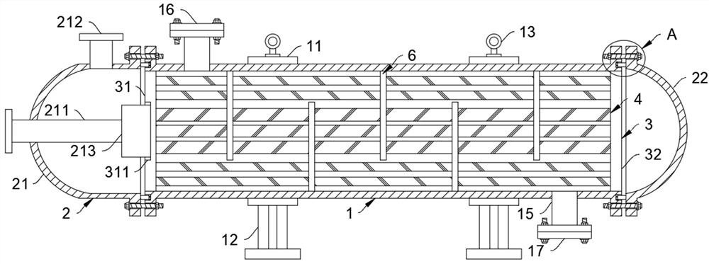
[0029] like Figure 1-6 As shown, a tube-sheet installation structure of a quick-connected tube-and-tube heat exchanger for chemical industry includes a shell 1. It should be noted that the shell 1 adopts a tubular structure, and the middle position of the shell 1 is symmetrically provided with a fixed ring 11. One end of the fixed ring 11 close to the ground is provided with a support 12 for supporting the equipment, and the end of the fixed ring 11 away from the ground is detachably connected with a lifting ring 13, which is convenient for the transfer and hoisting of the equipment and improves the flexibility of the transfer of the heat exchanger.

[0030] The shell 1 is fixedly connected with the pipe box 2 through the flange. It should be noted that the end of the pipe box 2 and the shell 1 close to each other is equipped with a flange, and the flan...


PUM


Abstract

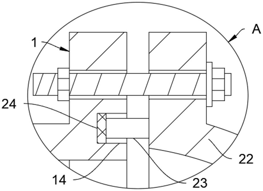
The invention belongs to the field of heat exchanger equipment, and particularly relates to a tube plate mounting structure of a quick-connection type tubular heat exchanger for chemical engineering.The tube plate mounting structure comprises a shell; a tube box is fixedly connected to the shell through a flange; tube plates are in threaded connection at the two ends, close to the tube box, of the shell; the tube box and the tube plates are arranged in a matched manner; heat exchange tubes are detachably connected to the tube plates; one end of each heat exchange tube is connected with one tube plate in a clamping manner, and the other end of the heat exchange tube is fixedly connected with the other tube plate through a limiting mechanism; and the heat exchange tubes are connected with the shell through baffle plates in a matched manner. According to the tube plate mounting structure, the heat exchange tubes which are detachably connected are arranged, the situation that normal use of equipment is affected by the condition of insufficient soldering or desoldering of welding spots in the welding process of the heat exchange tubes and the tube plates is avoided, meanwhile, workerscan effectively and conveniently conduct detection and replacement operation on the equipment, the labor intensity of the workers in the operation process is reduced, and the repair efficiency of theequipment is improved.

Description

technical field [0001] The invention belongs to the field of heat exchanger equipment, and in particular relates to a tube plate installation structure of a quick-connected tube-and-tube heat exchanger for chemical industry. Background technique [0002] A heat exchanger is a device that transfers part of the heat of a hot fluid to a cold fluid, also known as a heat exchanger. Heat exchangers play an important role in chemical, petroleum, power, food and many other industrial productions. In chemical production, heat exchangers can be used as heaters, coolers, condensers, oil coolers, evaporators and reboilers Wait. With the continuous popularization and expansion of the application of heat exchangers in the chemical industry, the deficiencies in the actual use of the tube-sheet installation structure of the quick-connect tube-and-tube heat exchanger for chemical industry also urgently need to be improved. [0003] At present, most of the heat exchange tubes and tube sheet...

Claims


Application Information

Patent Timeline
Patent Type & Authority Applications(China)
IPC IPC(8): F28D7/16F28F9/10F28F9/24F28F9/26
CPCF28D7/16F28F9/26F28F9/10F28F9/24
Inventor 孙丽颖
Owner 惠州忠信化工有限公司
Learn More