
Preparation method of flexible display panel

A flexible display and flexible substrate technology, applied in manufacturing tools, welding equipment, laser welding equipment, etc., can solve problems such as damage to the array film layer, low manufacturing yield of flexible display panels, and affecting the normal display of the display area

Pending Publication Date: 2021-01-01
FUJIAN HUAJIACAI CO LTD
View PDF4 Cites 3 Cited by
  • Summary
  • Abstract
  • Description
  • Claims
  • Application Information

AI Technical Summary

Problems solved by technology

However, due to the direct contact between the laser and the flexible substrate during the peeling process, the high energy released by the laser will cause damage to the array film layer of the device, affecting the luminous effect of the device, resulting in low manufacturing yield of the flexible display panel.
At the same time, when LLO is performed, cracks will be generated in the frame area of ​​the flexible panel. Over time, the cracks will continue to spread and eventually spread to the display area, affecting the normal display of the display area.

Method used


Image

  • Preparation method of flexible display panel
  • Preparation method of flexible display panel
  • Preparation method of flexible display panel

Examples


Embodiment Construction

[0031] In order to explain in detail the technical content, structural features, achieved goals and effects of the technical solution, the following will be described in detail in conjunction with specific embodiments and accompanying drawings.

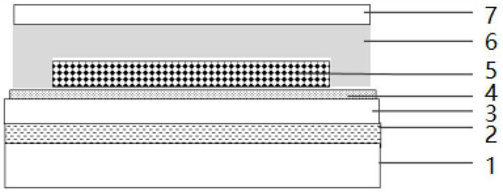
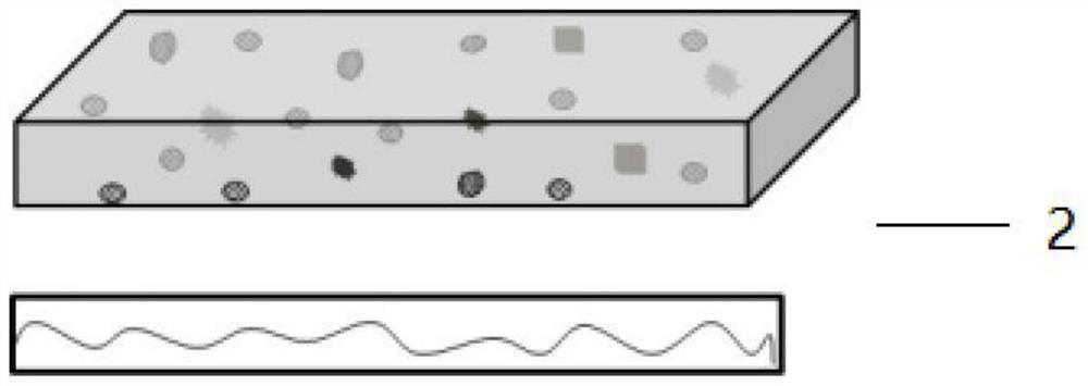
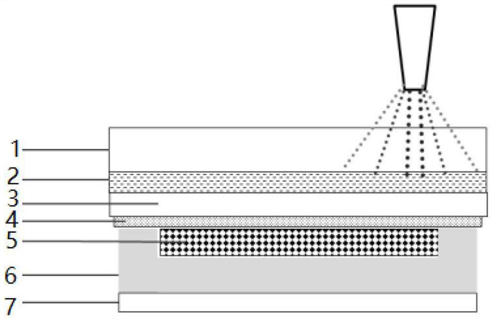
[0032] see Figures 1 to 5 , the present embodiment provides a method for preparing a flexible display panel, comprising the steps of: coating a material layer 2 on a substrate 1, the material layer 2 is used to absorb and reflect laser light; and coating the material layer 2 with Cloth the PI solution, heat up and dry the PI solution step by step to form a flexible substrate layer 3; make a TFT array film layer 4 on the flexible substrate layer 3; make a light emitting layer 5, and make a thin film encapsulation layer on the light emitting layer 5 6. The thin film encapsulation layer 6 is coated on the light-emitting layer 5; the flexible display panel with the substrate 1 is cut; the material layer 2 is irradiated with a laser, and ...


PUM


Abstract

The invention discloses a preparation method of a flexible display panel, and the method comprises the following steps: coating a material layer on a substrate, wherein the material layer is used forabsorbing and reflecting laser; coating a PI solution on the material layer, and heating and drying the PI solution in stages to form a flexible substrate layer; manufacturing a TFT array film layer on the flexible substrate layer; manufacturing a light-emitting layer, manufacturing a thin film packaging layer on the light-emitting layer, and coating the light-emitting layer with the thin film packaging layer; cutting the flexible display panel with the substrate; and irradiating the material layer by laser to separate the flexible substrate layer from the substrate. In the substrate strippingprocess, the interaction between laser and microscopic particles of a material on the surface of the material is a full-quantization energy exchange process. After the laser is incident to the surface of the material, part of the light energy with the energy of E0 is reflected, and the remaining energy is absorbed by the object. In the invention, the material layer absorbs and reflects the laser,and residual laser energy does not penetrate through the flexible substrate to influence the TFT array structure.

Description

technical field [0001] The invention relates to the field of manufacturing flexible display panels, in particular to a method for preparing a flexible display panel Background technique [0002] Organic Light Emitting Diode (OLED) displays have been widely used due to their simple fabrication process, low power consumption, high luminance, and wide color gamut. With the continuous development of display technology, flexible OLEDs are widely used in smart electronic devices, vehicle displays and various wearable devices due to their remarkable bendability, light weight and wide application range. And with the continuous development of personal intelligent terminal technology and the continuous increase of people's demand, flexible OLED will eventually become the display technology with the most development potential. Among them, the manufacturing process technology of flexible display devices is the key to affecting product yield and enterprise production efficiency. [000...

Claims


Application Information

Patent Timeline
Patent Type & Authority Applications(China)
IPC IPC(8): H01L27/32H01L21/78H01L51/00H01L21/77B23K26/36B23K26/00B23K101/40H10K99/00
CPCH01L21/7813B23K26/00B23K26/36B23K2101/40H10K59/12H10K71/80H10K77/111H10K59/1201Y02E10/549Y02P70/50
Inventor 孙玉俊黄逸臻张麒麟
Owner FUJIAN HUAJIACAI CO LTD
Learn More