Continous hot-rolling facility

a hot-rolling facility and hot-rolling mill technology, which is applied in the direction of rolling mill drives, metal rolling arrangements, manufacturing tools, etc., can solve the problems of difficulty in hot-rolling mill production, difficulty in carrying out such a rolling method, and insufficient steel sheet rolling capacity of lower rolling stands, so as to achieve smooth hot-rolling production and advantageous equipment cost and energy consumption

Inactive Publication Date: 2005-01-27
NAKAYAMA STEEL WORKS +1
View PDF6 Cites 2 Cited by
  • Summary
  • Abstract
  • Description
  • Claims
  • Application Information

AI Technical Summary

Benefits of technology

As mentioned above, in view of the influence of rolling action on the metallographic structure, the upper rolling stands of the continuous hot-rolling mill do not need to roll the steel sheet at particularly high draft in producing a hot-rolled, fine-grained steel sheet. On the other hand, it is preferable that the lower rolling stands including the last rolling stand roll the steel sheet at high drafts to increase the cumulative strain to 0.9 or above. Therefore, the continuous hot-rolling mill including the two or more lower rolling stands, namely, the differential or very-small-diameter rolling stands, provided with the drive motors having the capacities considerably larger than those of the motors of the upper rolling stands is a reasonable, viable continuous hot-rolling mill capable of smoothly producing a hot-rolled, fine-grained steel sheet. Since the rolling stands of the upper rolling unit that roll the steel sheet at low drafts are provided with the drive motors having capacities considerably smaller than those of the drive motors of the rolling stands of the lower rolling unit, the continuous hot-rolling mill is economically advantageous. It is particularly advantageous in equipment cost and energy consumption to provide the last rolling stand with a motor having the maximum capacity for the aforesaid reasons.

Problems solved by technology

The conventional continuous hot-rolling mill has difficulties in producing a hot-rolled, fine-grained steel sheet having fine ferrite structures and high mechanical properties.
However, the conventional continuous hot-rolling mill having the rolling stands provided with motors having the capacities explained above has difficulty in carrying out such a rolling method.
Even if the lower rolling stands are provided with motors each having a relatively large capacity as mentioned in ii and iii), the lower rolling stands do not have a rolling capacity to roll the steel sheet at a high draft by using a high rolling force.
Even if the motor of the lower rolling stand has an excess capacity and the lower rolling stand is able to roll the steel sheet at a sufficiently high draft, it is impossible to solve problems relating to the meandering and shape deterioration of thin steel sheets

Method used


Image

  • Continous hot-rolling facility
  • Continous hot-rolling facility
  • Continous hot-rolling facility

Examples


examples

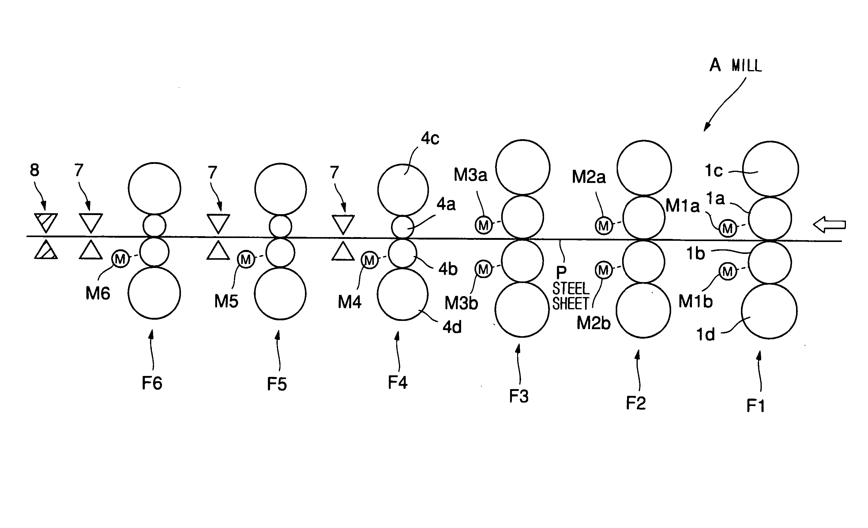
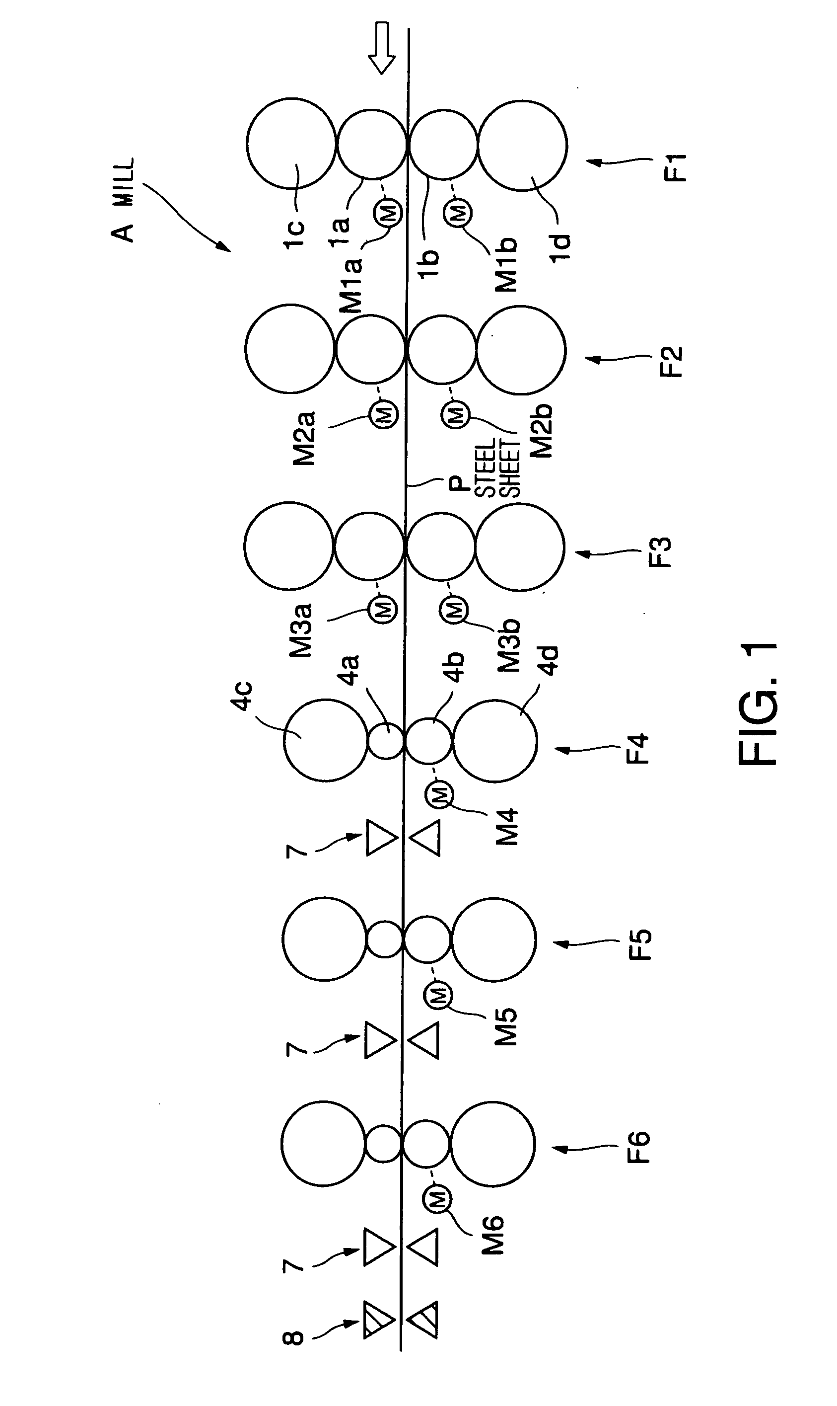
A pass schedule for the continuous hot-rolling mill A, and the distribution of the respective capacities of the drive motors of the rolling stands F1 to F6 will be described by way of example.

The continuous hot-rolling mill A is operated to produce a steel sheet of 2.3 mm in thickness and 1200 mm in width by rolling a steel workpiece containing 0.16% C, 0.22% Si and 0.82% Mn (not containing other substances in significant content). The continuous hot-rolling mill A operates at a rolling speed at which general hot strip mills operate. For example, the continuous hot-rolling mill A operates at a rolling speed in the range of 7 to 9 m / s.

Table 1 shows a general pass schedule for ordinary rolling for producing general-purpose steel sheets which are not fine-grained steel sheets. It may be proper to provide the rolling stands F1 to F6 with drive motors having capacities shown in Table 2 (which are distributed in a conventional capacity distribution) to carry out a rolling operation s...


PUM

PropertyMeasurementUnit
diameteraaaaaaaaaa
flatnessaaaaaaaaaa
rolling force distributionaaaaaaaaaa

Abstract

A continuous hot-rolling mill includes an upper rolling unit including a plurality of rolling stands, and a lower rolling unit including a plurality of rolling stands and disposed downstream with respect to the upper rolling unit in a workpiece passing direction in which a workpiece to be rolled is passed. The two or more rolling stands of the lower rolling unit are differential or very-small-diameter rolling stands. Each of the two or more differential or very-small-diameter rolling stands of the lower rolling unit is provided with a drive motor having a capacity greater than that of any one of drive motors included in the rolling stands disposed upstream the differential or very-small-diameter rolling stands. The continuous hot-rolling mill is suitable for producing hot-rolled, fine-grained steel sheets and is excellent in sheet passing abilities for preventing the steel sheet from meandering and for rolling the steel sheet in a desired shape.

Description

TECHNICAL FIELD The present invention relates to a continuous hot-rolling mill suitable for manufacturing a hot-rolled fine-grained steel sheet of fine structure mainly of fine ferrite grains. BACKGROUND ART In hot-rolling a thin steel sheet by a continuous hot-rolling mill (finishing mill) formed by arranging five to seven rolling stands in a tandem arrangement, a pass schedule is designed, in most cases, to place a maximum rolling load on the second or the third rolling stand. Such a pass schedule is recommended because a) the workpiece fed to the first rolling stand is thick and the workpiece is not pushed from the upper side into the first rolling stand, and hence the leading end of the thick workpiece cannot be gripped between the rolls if rolling force is excessively high, and b) the workpiece tends to meander and the shape of the workpiece, such as flatness, is deteriorated if an excessively high rolling force is exerted on the workpiece by the lower rolling stands at a low...

Claims


Application Information

Patent Timeline
Patent Type & Authority Applications(United States)
IPC IPC(8): B21B1/26B21B13/14B21B45/02
CPCB21B1/26B21B13/142B21B45/0233B21B2275/12B21B2267/065B21B2275/10B21B2267/06
Inventor KURAHASHI, RYUROUUENO, SHINJIKOMATSU, TAKAYOSHITAKAHASHI, MASANORIADACHI, AKIOTAKAOKA, SHINJI
Owner NAKAYAMA STEEL WORKS
Why Eureka
Try Eureka