

Building reinforcing steel bar cutting device
A cutting device and technology for construction, applied in the field of construction, can solve problems such as difficulty in ensuring the stability of steel bars, low cutting efficiency, and easy splashing of iron filings, and achieve good application prospects, simple structure, and improved straightening effect
- Summary
- Abstract
- Description
- Claims
- Application Information
AI Technical Summary
Problems solved by technology
Method used
Image

Examples
Embodiment 1
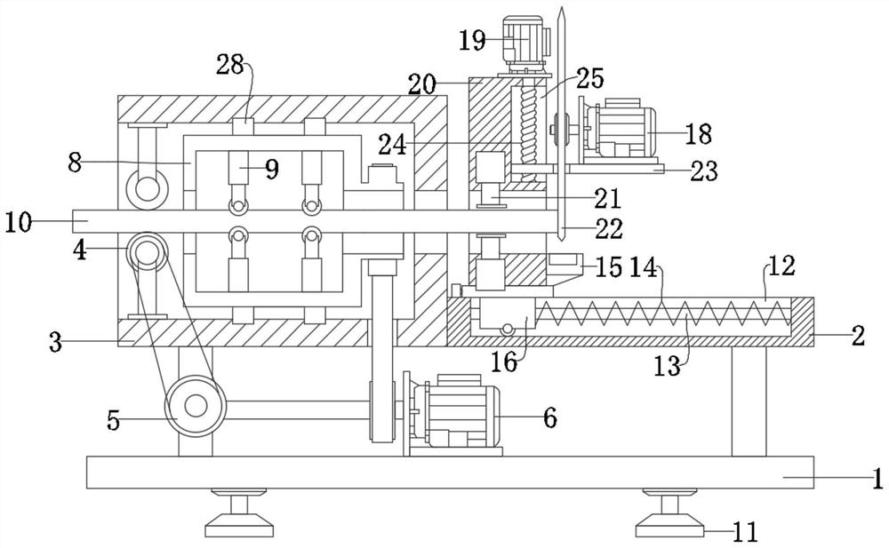
[0022] see Figure 1-2 , a cutting device for steel bar 10 for construction, comprising a bottom plate 1, a steel bar 10, a box body 3 and a carrier plate 2, wherein the box body 3 and the carrier plate 2 are fixedly connected, and the box body 3 and the carrier plate 2 pass through a column Fixedly connected to the bottom plate 1, and a cutting assembly is installed on the carrier plate 2, and the effective cutting of the steel bar 10 is further realized through the cutting assembly; a straightening assembly is installed in the box body 3, The effective straightening process of the box body 3 is further realized through the straightening assembly, the actual production quality of the steel bar 10 is further improved, and the actual cutting effect of the steel bar 10 is subsequently achieved, and a drive is installed at the entrance position of the box body 3 assembly, through which the driving assembly further drives the movement of the steel bar 10 in the device; further, th...
Embodiment 2
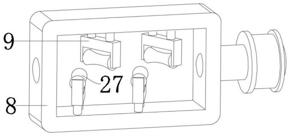
[0028] This embodiment further explains the straightening assembly on the basis of the above embodiments, specifically, the straightening assembly includes a straightening wheel 27, a rotating box 8, a limit block 28 and a straightening wheel 27, Wherein, the limit block 28 is fixedly connected to the side of the rotating box 8, and an annular slide rail is provided on the inner surface of the box body 3, and the limit block 28 is slidably arranged in the annular slide rail, so that the The above-mentioned rotating box 8 can rotate in the box body 3; the rotating shaft of the rotating box 8 and the transfer motor 6 is connected by a belt transmission, so that the transfer motor 6 can further drive the rotating box when driving the steel bar 10 to move. 8 rotation; described straightening wheel 27 is rotated and installed on the straightening frame 9, and described straightening frame 9 is rotated and installed in the box body 3, and is installed along the opposite side of rotat...
PUM
 Abstract
Description
Claims
Application Information