Long nozzle replacement method and equipment based on visual servo, terminal and medium

A technology of visual servoing and replacement methods, which is applied in the direction of casting equipment, metal processing equipment, manufacturing tools, etc., can solve the problems of high risk, high temperature, and inability to realize automation, etc., and achieves simple and easy implementation, automation, and practicability and high applicability

Active Publication Date: 2021-01-05
CISDI ENG CO LTD +1
View PDF13 Cites 0 Cited by
  • Summary
  • Abstract
  • Description
  • Claims
  • Application Information

AI Technical Summary

Problems solved by technology

[0003] In related technologies, for the metallurgical continuous casting production site, the modern continuous casting machine adopts the shroud manipulator to realize the replacement of the shroud by the electromechanical drive device instead of manual replacement of the shroud, but it cannot be fully automated, and workers still need to operate on site
Due to the high temperature and high risk of the continuous casting tundish operation site, the labor risk of workers is relatively high

Method used


Image

  • Long nozzle replacement method and equipment based on visual servo, terminal and medium
  • Long nozzle replacement method and equipment based on visual servo, terminal and medium
  • Long nozzle replacement method and equipment based on visual servo, terminal and medium

Examples


Embodiment 1

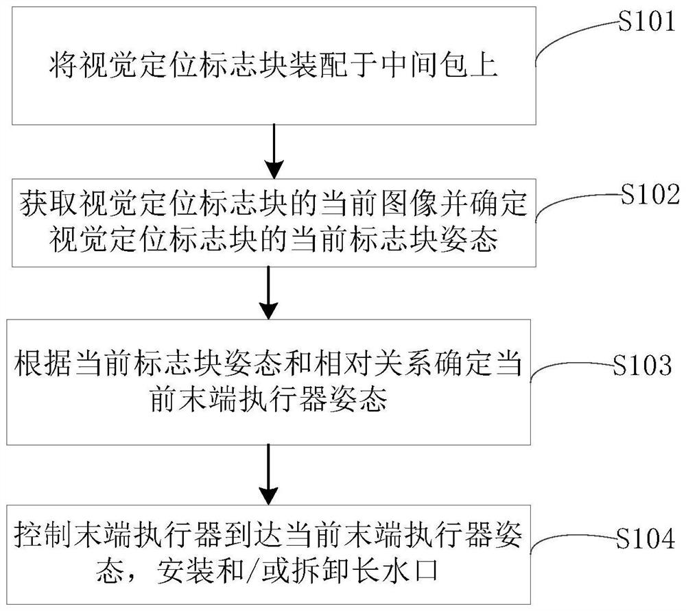
[0054] see figure 1 , the embodiment of the present invention provides a method for replacing a shroud based on visual servoing, including:

[0055] S101: Assembling the visual positioning mark block on the tundish.

[0056] In some embodiments, the visual positioning marker block is fixedly installed on the slide mechanism of the continuous casting tundish.

[0057] In some embodiments, the visual positioning marker block includes at least 3 different sub-marker blocks.

[0058] In some embodiments, the visual positioning sign block includes at least two background color backgrounds, and the current background color background of the visual positioning sign block is determined according to the on-site background color background. Optionally, the outline shapes of the sub-markers are the same, and the sizes of the sub-markers are different.

[0059] Optionally, the size of each sub-marker block can be adjusted according to actual working conditions, which is not limited her...

Embodiment 2

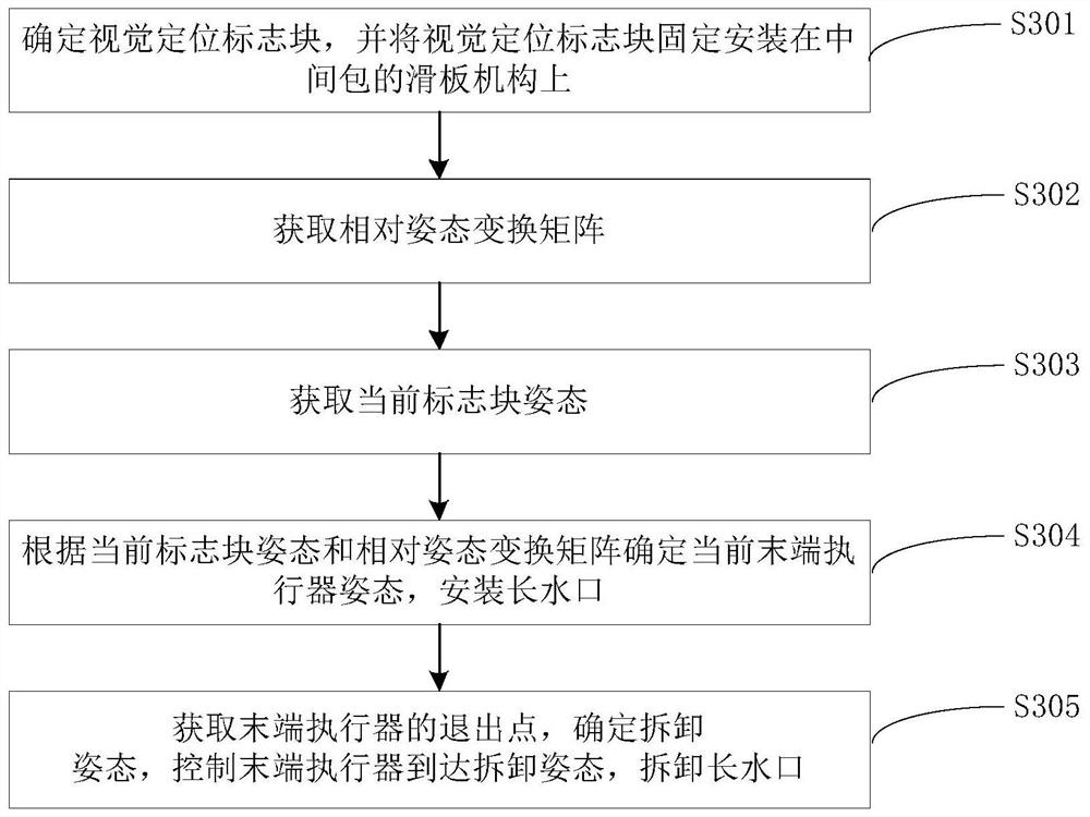
[0132] The method for replacing a long shroud based on visual servoing provided by this embodiment is exemplarily described below through a specific embodiment, see: image 3 , the specific method for replacing the long shroud based on visual servoing includes:

[0133] S301: Determine the visual positioning mark block, and fix the visual positioning mark block on the sliding plate mechanism of the tundish.

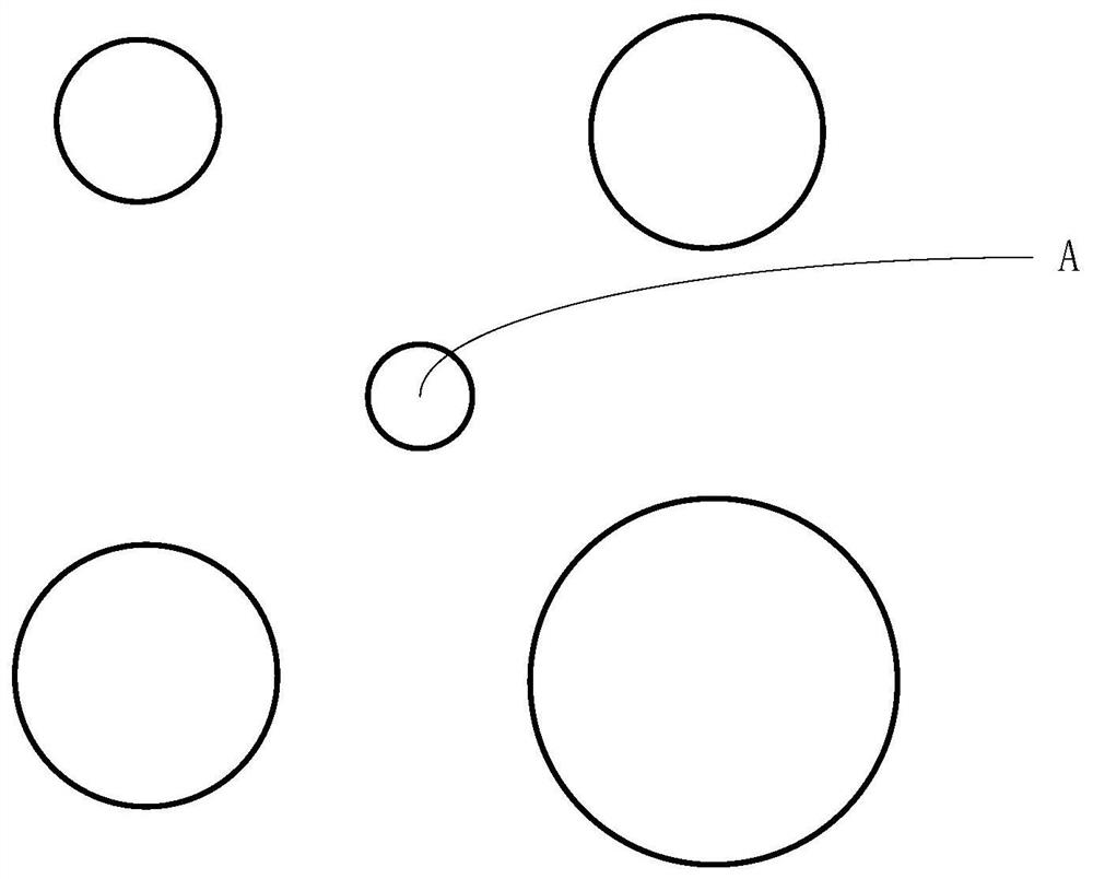
[0134] In some embodiments, the outline of the visual locator block is a circular outline.

[0135] Optionally, the background color, background, shape and size of the visual positioning marker block and the radius of the circle outline can be determined according to the on-site environment. After the design and processing of the visual positioning marker block is completed, the relative positional relationship between the centers of the circle outlines is recorded.

[0136] In some embodiments, the schematic diagram of the structure of each sub-marker block on the visua...

Embodiment 3

[0165] see Figure 4 , a shroud replacement device 400 based on visual servoing, comprising:

[0166] An assembly module 401, configured to assemble the visual positioning marker block on the tundish;

[0167] The current marker block posture acquisition module 402 is used to acquire the current image of the visual positioning marker block and determine the current marker block posture of the visual positioning marker block;

[0168] A determining module 403, configured to determine the current end effector pose according to the current marker block pose and the relative relationship, the relative relationship including a mapping between the marker block pose and the end effector pose;

[0169] The control module 404 is used to control the end effector to reach the current end effector attitude, and install and / or remove the shroud.

[0170] In this embodiment, the shroud replacement device based on visual servoing is essentially equipped with a plurality of modules to execu...


PUM


Abstract

The invention provides long nozzle replacement method and equipment based on visual servo, a terminal and a medium. The method comprises the steps: assembling a visual positioning mark block on a tundish, obtaining a current image comprising the visual positioning mark block, determining the current mark block posture of the visual positioning mark block, determining a current end effector postureaccording to the current mark block posture and a relative relationship including mapping between the mark block posture and the end effector posture, controlling an end effector to reach the currentend effector posture, and mounting and/or dismounting a long nozzle. The invention further provides the long nozzle replacement equipment based on visual servo, the terminal and the medium, the corresponding current end effector posture is determined according to different positions of the tundish, a robot is guided to reach the current end effector posture point to complete the replacement workof the long nozzle, automation of long nozzle replacement is achieved, high-strength and high-risk manual operation is replaced, the method is simple and easy to implement, and the practicability andthe applicability are high.

Description

technical field [0001] The invention relates to the field of industrial automation, in particular to a visual servo-based shroud replacement method, equipment, terminal and medium. Background technique [0002] In the tundish platform of the iron and steel metallurgical continuous casting process, the equipment connecting the ladle and the tundish is called the shroud, also known as the protective sleeve, which is installed under the ladle and connected to the water outlet of the slide mechanism. The shroud has a certain service life, and it needs to be loaded and unloaded regularly during the continuous casting tundish operation. [0003] In related technologies, for the metallurgical continuous casting production site, the modern continuous casting machine uses the shroud manipulator to realize the replacement of the shroud by the electromechanical drive device instead of manual replacement of the shroud, but it cannot be fully automated, and workers still need to operate ...

Claims


Application Information

Patent Timeline
Patent Type & Authority Applications(China)
IPC IPC(8): B22D41/56
CPCB22D41/56
Inventor 刘贵林谭云龙张燕彤刘景亚
Owner CISDI ENG CO LTD
Why Eureka
Try Eureka