Cutting device with waste material collecting and treating function for hardware machining

A cutting device and utensil technology, applied in shearing devices, metal processing equipment, accessories of shearing machines, etc., can solve the problems of inability to fix workpieces, operator injury, insufficient precision cutting accuracy, etc., to ensure cutting processing accuracy. , to ensure the effect of stability

Active Publication Date: 2021-01-05
林慧丽
View PDF8 Cites 0 Cited by
  • Summary
  • Abstract
  • Description
  • Claims
  • Application Information

AI Technical Summary

Problems solved by technology

[0003] In the existing hardware processing and cutting process, it is easy to accumulate cutting waste materials on the operation table, which can easily affect the cutting processing of other hardware parts later, and the cutting hardware waste materials cannot be processed in time. It is easy to cause injury to the operator, and the cutting process is not stable enough, resulting in insufficient precision cutting accuracy, and at the same time, the workpiece cannot be fixed quickly and easily. Therefore, it is necessary to invent a cutting device for metal processing with the function of collecting and processing waste materials

Method used


Image

  • Cutting device with waste material collecting and treating function for hardware machining
  • Cutting device with waste material collecting and treating function for hardware machining
  • Cutting device with waste material collecting and treating function for hardware machining

Examples


Embodiment Construction

[0027] The following will clearly and completely describe the technical solutions in the embodiments of the present invention with reference to the accompanying drawings in the embodiments of the present invention. Obviously, the described embodiments are only some, not all, embodiments of the present invention. Based on the embodiments of the present invention, all other embodiments obtained by persons of ordinary skill in the art without making creative efforts belong to the protection scope of the present invention.

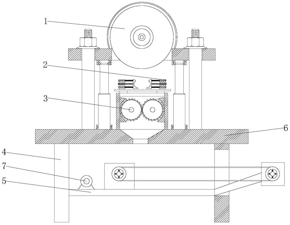
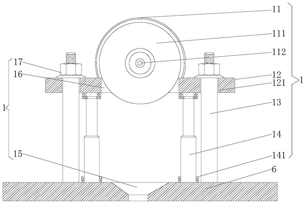
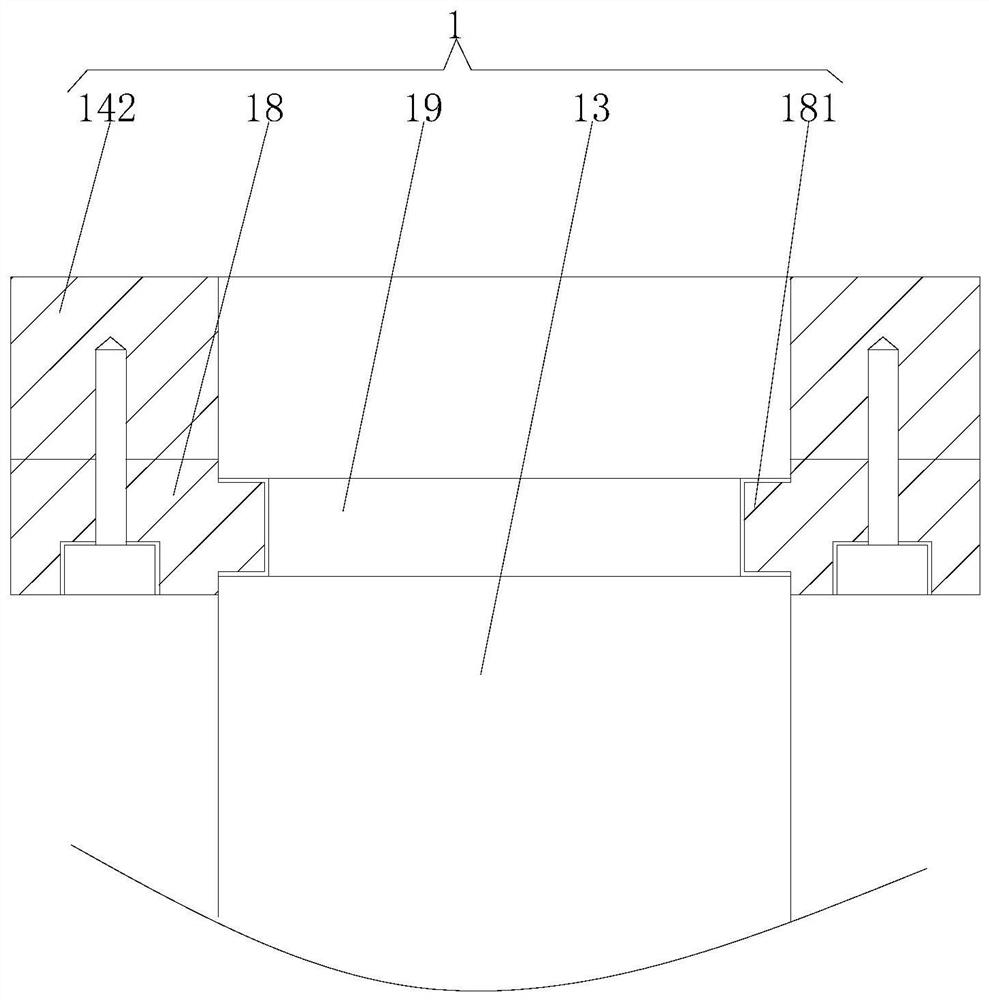
[0028] see Figure 1-7 , the present invention provides a technical solution: a cutting device with the function of collecting and processing waste materials for metal processing, including a cutting mechanism 1, a fixing mechanism 2, a crushing mechanism 3, supporting legs 4, a fixing plate 5, an operating table 6 and The power mechanism 7, the top of the support leg 4 is fixedly connected to the bottom of the console 6, the middle part of the inner side of t...


PUM


Abstract

The invention discloses a cutting device with a waste material collecting and treating function for hardware machining. The cutting device comprises a cutting mechanism, a fixing mechanism, a smashingmechanism, supporting legs, a fixing plate, an operation table and a power mechanism, the tops of the supporting legs are fixedly connected with the bottom of the operation table, and the middles ofthe inner sides of the supporting legs are fixedly connected with the four corners of the fixing plate. The left side of the top of the fixing plate is fixedly connected with the bottom of the power mechanism, the position, close to the right side of the power mechanism, of the top of the fixing plate is fixedly connected with the bottom of the smashing mechanism, and the top of the operation table is fixedly connected with the bottom of the cutting mechanism. According to the cutting device with the waste material collecting and treating function for hardware machining, when the cutting device is used, a cutting wheel can be directly driven to descend through a hydraulic lifting rod, at the moment, a first motor works to drive the cutting wheel to rotate, and hardware fixed to the fixingmechanism can be evenly cut and machined; and an arranged positioning rod can further guarantee the stability of the cutting wheel in the cutting process, and the cutting machining precision is guaranteed.

Description

technical field [0001] The invention relates to the technical field of hardware processing, in particular to a cutting device for metal processing with the function of collecting waste materials. Background technique [0002] Hardware processing is to process raw materials (stainless steel, copper, aluminum, iron...) into various parts with lathes, milling machines, drilling machines, polishing and other machines according to customers' drawings or samples. Such as: screws, motor shafts, model car parts, fishing tackle accessories, speaker product shells, mobile power shells, etc. [0003] In the existing hardware processing and cutting process, it is easy to accumulate cutting waste materials on the operation table, which can easily affect the cutting processing of other hardware parts later, and the cutting hardware waste materials cannot be processed in time. It is easy to cause injury to the operator, and the cutting process is not stable enough, resulting in insufficie...

Claims


Application Information

Patent Timeline
Patent Type & Authority Applications(China)
IPC IPC(8): B23D19/00B23D33/00B23D33/02B02C4/08B02C4/28
CPCB02C4/08B02C4/28B23D19/00B23D33/00B23D33/02
Inventor 王立英
Owner 林慧丽
Why Eureka
Try Eureka