Fine stamping deflashing machine for die machining

A technology of mold processing and flashing machine, which is applied in the direction of metal processing machinery parts, metal processing, metal processing equipment, etc., can solve the problems of waste, affecting processing efficiency, improper treatment of oxide layer, etc., achieve strong cleaning ability and improve processing efficiency , The effect of improving the accuracy of deflashing

Inactive Publication Date: 2021-01-05
衡阳市振洋汽车配件有限公司
View PDF7 Cites 0 Cited by
  • Summary
  • Abstract
  • Description
  • Claims
  • Application Information

AI Technical Summary

Problems solved by technology

[0004] 1. The existing flashing machine has poor limit ability and insufficient processing accuracy;
[0005] 2. The existing flashing machine, the dust generated when the equipment is idle and the debris generated when processing the flashing, can easily affect the normal operation of the equipment;
[0006] 3. In the existi

Method used


Image

  • Fine stamping deflashing machine for die machining
  • Fine stamping deflashing machine for die machining
  • Fine stamping deflashing machine for die machining

Examples


Embodiment Construction

[0039] The following will clearly and completely describe the technical solutions in the embodiments of the present invention with reference to the accompanying drawings in the embodiments of the present invention. Obviously, the described embodiments are only some, not all, embodiments of the present invention. Based on the embodiments of the present invention, all other embodiments obtained by persons of ordinary skill in the art without making creative efforts belong to the protection scope of the present invention.

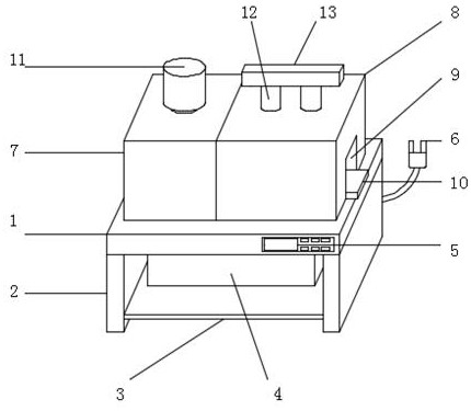
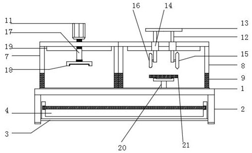
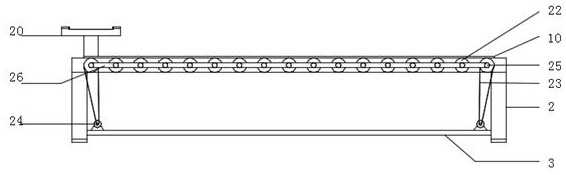
[0040] see Figure 1-7 , in this embodiment: including workbench 1, support 2 is arranged on both sides of the bottom end of workbench 1, connecting frame 3 is erected between two groups of supports 2, and the upper end of connecting frame 3 is located between two groups of supports 2 and is provided with a water tank 4. A control panel 5 is installed on the front end of the workbench 1, a power interface 6 is installed on the bottom of the back of the workben...


PUM


Abstract

The invention discloses a fine stamping deflashing machine for die machining which includes a workbench, wherein brackets are arranged on the two sides at the bottom end of the workbench; a connectingframe is erected between the two groups of brackets; a water tank between the two groups of brackets is positioned at the upper end of the connecting frame; a cleaning device is arranged on one sideon the outer surface at the upper end of the workbench; a treatment device is arranged at one end, at the upper end of the workbench, of the cleaning device; a rotating motor is arranged at the upperend of the cleaning device; two groups of first connecting rods are arranged at the upper end of the treatment device in a penetrating manner; a first cutting wheel and a second cutting wheel are arranged at the bottom end of each group of first electric telescopic rod; a die to be treated is clamped at the upper end of a clamping frame. According to the fine stamping deflashing machine for die machining, the two groups of cutting wheels improve the flash treatment efficiency and effectively reduce damage to the die; through arranging a blasting mechanism and a water tank, dust generated whenthe machine is in idle and scraps generated during operation can be treated, so that the stable operation of the equipment can be guaranteed.

Description

technical field [0001] The invention relates to the technical field of mold processing, in particular to a flashing machine for precision mold processing. Background technique [0002] Mold processing refers to the processing of forming and billet tools, and also includes shearing dies and die-cutting dies. Usually, the mold consists of two parts, the upper mold and the lower mold. The steel plate is placed between the upper and lower molds, and the material is formed under the action of the press. When the press is opened, the workpiece determined by the shape of the mold is obtained or the corresponding waste is removed. Workpieces as small as electronic connectors and as large as automotive dashboards can be molded. Progressive die refers to a set of molds that can automatically move the workpiece from one station to another, and obtain formed parts at the last station. Mold processing technology includes: cutting die, punching die, compound die, extrusion die, four-sl...

Claims


Application Information

Patent Timeline
IPC IPC(8): B23P23/02B23Q7/00B23Q11/00B08B1/04B08B1/00B08B5/02B01D46/10
CPCB23P23/02B23Q7/00B23Q11/00B08B1/04B08B1/006B08B5/02B01D46/10
Inventor 佟艳军谢亚平肖泉
Owner 衡阳市振洋汽车配件有限公司
Why Eureka
Try Eureka