TIG girth welding device and TIG girth welding process for bottom of storage tank

A technology for girth welding and storage tanks, which is applied in the direction of manufacturing tools, welding equipment, welding accessories, etc., can solve the problem of low girth welding accuracy at the bottom of storage tanks, meet the requirements of high-precision welding, accurate and stable positions, and facilitate milling Effects of edges and welds

Pending Publication Date: 2021-01-05
厦门中科伊贝格机械有限公司
View PDF0 Cites 1 Cited by
  • Summary
  • Abstract
  • Description
  • Claims
  • Application Information

AI Technical Summary

Problems solved by technology

[0006] Aiming at the deficiencies of the prior art, the present invention provides a TIG girth welding device and a TIG girth welding process for the bottom of the storage tank, which solves the problem of low precision of the girth welding of the bottom of the storage tank

Method used


Image

  • TIG girth welding device and TIG girth welding process for bottom of storage tank
  • TIG girth welding device and TIG girth welding process for bottom of storage tank
  • TIG girth welding device and TIG girth welding process for bottom of storage tank

Examples


Embodiment 1

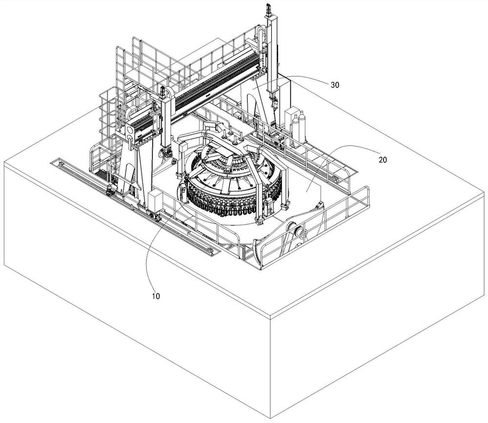
[0064] like Figure 2-7 As shown, the present invention provides a TIG girth welding device at the bottom of a storage tank. The TIG girth welding device includes: a girth welding tire tool 10, a positioner 20 and a milling and welding gantry 30; the girth welding tire The tool 10 is installed on the positioner 20, and the milling and welding gantry 30 is erected above the girth welding tool 10; the girth welding tool 10 clamps and positions the components to be welded at the bottom of the tank, and the variable The positioning machine 20 drives the circumferential seam welding tool 10 to displace, and cooperates with the milling and welding gantry 30 to perform edge milling and TIG circumferential seam welding at the weld;

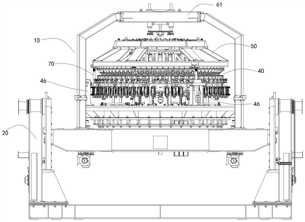
[0065] The girth welding tire 10 includes: a welding mold tire 40, a pressing device 50 and a top cover pressure ring 60;

[0066] The welding mold tire 40 includes: a base 41, a lifting ring 42, a supporting device 43, a mandrel lifting device 44 and a ...

Embodiment 2

[0082] The present invention provides a TIG girth welding process using the TIG girth welding device described in Embodiment 1, and the TIG girth welding process includes the following steps in turn:

[0083] S1: Fork ring clamping

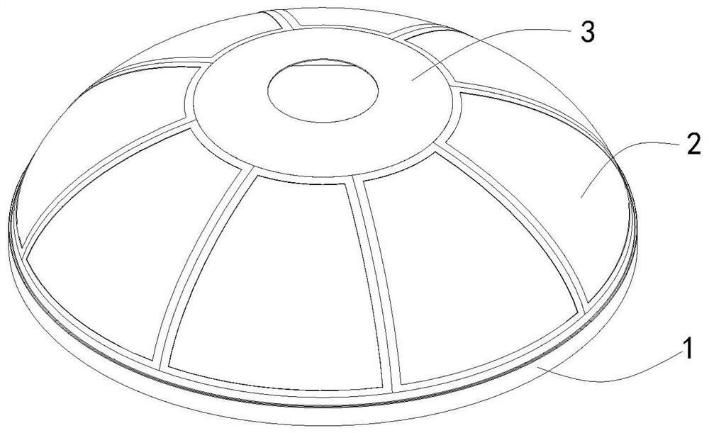
[0084] The hoisting fork ring 1 is placed on the lifting ring 42, the first inner support 421 is driven, and the fork ring 1 is tightened and fixed from the inside; the first piano key pressing block 422 is driven by the air cylinder, and the fork ring 1 is pressed from the outside, Realize the clamping and fixing of the fork ring 1;

[0085] S2: ring clamping

[0086] Place the hoisting ring 2 on the supporting device 43, drive the second inner support 431, and tighten and fix the hoop ring 2 from the inside; hoist the pressing device 50, insert the centering sleeve 541 into the centering hole 441, and fix the centering sleeve 541 through the bolt. The positioning assembly 54 is connected with the mandrel elevating device 44, drives the second ...


PUM


Abstract

The invention provides a TIG girth welding device and a TIG girth welding process for the bottom of a storage tank, and relates to the technical field of TIG girth welding. The TIG girth welding device comprises a girth welding mold, a positioner and a milling and welding gantry. The girth welding mold comprises a welding mold, a pressing device and a top cover pressing ring. The welding mold comprises a base, a lifting ring, a supporting device, a mandrel lifting device and a connecting cylinder. The TIG girth welding process sequentially comprises the following steps that S1, a fork-shaped ring is clamped; S2, a circular ring is clamped; S3, edge milling is conducted; S4, welding is performed; S5, the pressing device is locked; S6, edge milling is conducted; S7, a top cover is clamped; S8, edge milling is conducted; S9, welding is performed; and S10, form removal and part taking are carried out. According to the TIG girth welding device and the TIG girth welding process for the bottom of the storage tank, servo driving of a motion unit is achieved, pressing is realized pneumatically, the welding device can be adapted to changes of the thickness of the bottom wall of the storage tank, after a workpiece is pressed on the welding mold, a milling head mills out allowance and a welding groove, the motion trail during milling is consistent with the motion trail during welding, andthe quality of welding butt joints is guaranteed; and the high-precision welding requirement of the product is effectively ensured.

Description

technical field [0001] The invention relates to the technical field of TIG girth welding, in particular to a tank bottom TIG girth welding device and a TIG girth welding process. Background technique [0002] The storage tank is a kind of pressure vessel, and it is also used as a load-bearing structure. There is an ellipsoid bottom at each end of the tank, such as figure 1 As shown, the bottom of the storage tank is composed of a fork ring 1, a ring 2 and a top cover 3, wherein the ring 2 is made of a plurality of melon petals through longitudinal welding. [0003] Since the bottom of the box is an ellipsoid, the welding edge area is a curved surface, and the bottom of the box is a large-diameter thin-walled aluminum alloy structure, it is difficult to weld and clamp, and the quality control is difficult. During the welding process of the girth seam at the bottom of the box, it is required that the welding edges of all welds such as the fork ring 1, the ring 2 and the top c...

Claims


Application Information

Patent Timeline
Patent Type & Authority Applications(China)
IPC IPC(8): B23P23/04B23K9/167B23K9/235B23K9/32
CPCB23K9/167B23K9/235B23K9/32B23P23/04
Inventor 邵传伟林海梁李光王赫群
Owner 厦门中科伊贝格机械有限公司
Why Eureka
Try Eureka