
A kind of electromagnetic support type drilling and anchoring machine and anchoring method

An all-in-one, electromagnetic technology, applied in drilling equipment and methods, rotary drilling rigs, drilling pipes, etc., can solve the problems of complex anchoring process, long operation time, low anchoring efficiency, etc., and save pre-drilling process and effect. The effect of short time and improved anchoring efficiency

Active Publication Date: 2022-08-02
AVIC GEOTECHN ENG INST
View PDF0 Cites 0 Cited by
  • Summary
  • Abstract
  • Description
  • Claims
  • Application Information

AI Technical Summary

Problems solved by technology

[0005] In view of the above-mentioned shortcomings and deficiencies of the prior art, the present invention provides an electromagnetic support type drilling and anchoring integrated machine and an anchoring method, which solves the problems of complex anchoring procedures, long operation time, low anchoring efficiency and high anchoring cost in the prior art. question

Method used


Image

  • A kind of electromagnetic support type drilling and anchoring machine and anchoring method
  • A kind of electromagnetic support type drilling and anchoring machine and anchoring method
  • A kind of electromagnetic support type drilling and anchoring machine and anchoring method

Examples


Embodiment 1

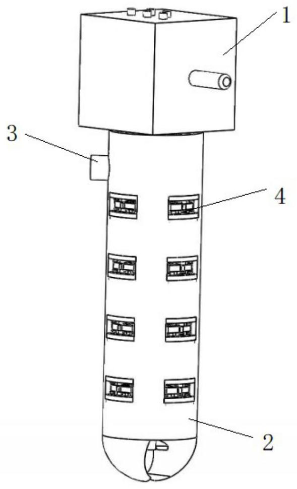
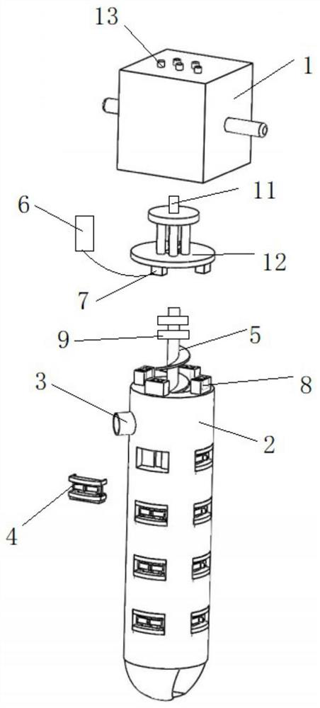
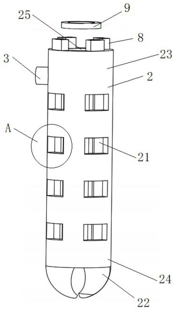
[0064] see Figure 1 to Figure 12 , the present invention provides an electromagnetic support type drilling-anchor integrated machine, comprising a driving device 1, an anchor rod 2 and a plurality of electromagnetic anchoring devices 4 arranged on the outer peripheral wall of the anchor rod 2, and the plurality of electromagnetic anchoring devices 4 are arranged along the The circumferential direction is arranged in rows, at least two rows, and the multiple electromagnetic anchoring devices 4 in each row are evenly arranged in the axial direction of the bolt 2 . The electromagnetic anchoring device 4 is used for inserting into the wall of the anchor hole to play a supporting role. The electromagnetic anchoring device 4 includes an anchoring device 45 and an electromagnetic device 46 . The anchor rod 2 has opposite first end parts 23 and second end parts 24, and the anchor rod 2 extends between the first end part 23 and the second end part 24 in a rod shape. In this embodiment...

Embodiment 2

[0078] On the basis of the first embodiment, the electromagnetic support type drilling-bolt integrated machine described in this embodiment has changed the connection structure of the soil removal device 5 and the second gear shaft 124. In this embodiment, the soil removal device 5 and the second gear shaft 124 have been changed. The second gear shaft 124 is connected through the locking sleeve 10, and the specific connection structure is as follows:

[0079] see Figure 13 and Figure 14 , the soil removal device 5 is fixedly connected with the second gear shaft 124 through the locking sleeve 10 . Specifically, the locking sleeve 10 has a hollow structure, specifically a cylindrical shape. One end is provided with a single row of clamping edges 102 pointing toward the center, and the other end is an internal thread 101 structure. The clamping edge 71 can be an annular inner flange, or can be a plurality of arc-shaped flanges spaced along the circumferential direction of th...


PUM


Abstract

The invention relates to an electromagnetic support type drilling-anchor integrated machine and an anchoring method, comprising a driving device, an anchor rod and a plurality of electromagnetic anchoring devices arranged on the outer peripheral wall of the anchor rod. One end of the anchor rod is provided with a cutter head, and the driving device is detachably and fixedly connected to the other end of the anchor rod, and can drive the anchor rod to rotate, so as to drive the cutter head to drill the anchor hole. The bolt is provided with a through hole, a soil removal device is sleeved in the through hole, the soil removal device is detachably connected with the driving device, and the drilled slag is discharged from the soil discharge hole under the driving of the driving device. The soil discharge hole is arranged on the outer peripheral wall of the bolt and communicated with the through hole. An electromagnetic driving unit is arranged on the driving device. After drilling, the electromagnetic anchoring device is controlled by the electromagnetic driving unit to be inserted into the wall of the anchor hole for support. During recovery, the electromagnetic anchoring device is controlled by the electromagnetic drive unit to pull out the wall of the anchor hole, and then the anchor rod is recovered. It integrates drilling and support, saves the pre-drilling process, improves the anchoring efficiency, and reduces the anchoring cost.

Description

technical field [0001] The invention relates to the technical field of geotechnical engineering reinforcement, in particular to an electromagnetic support type drilling-bolt integrated machine and an anchoring method. Background technique [0002] Anchor rod is a main form of support in water conservancy and hydropower engineering, underground engineering, foundation pit engineering and slope engineering. more obvious. [0003] At this stage, when the anchor rod is anchored and supported, it is necessary to drill the anchor hole with a drilling machine or a pile driver in advance, and then carry out the support. The operation process is complicated and the operation time is long, which greatly reduces the anchoring efficiency. The anchor rod is not recyclable, resulting in waste of steel and increasing the cost of anchoring. SUMMARY OF THE INVENTION [0004] (1) Technical problems to be solved [0005] Aiming at the above shortcomings and deficiencies of the prior art, ...

Claims


Application Information

Patent Timeline
Patent Type & Authority Patents(China)
IPC IPC(8): E21B7/00E21B3/02E21B17/22E21D20/00E02D5/74
CPCE21B7/005E21B3/02E21B17/22E21D20/003E02D5/74
Inventor 魏英杰王笃礼介玉新李建光柯尊东李家旺
Owner AVIC GEOTECHN ENG INST
Learn More