A Beaded Turbine Blade Trailing Edge Slit Cooling Structure

A technology of turbine blade and cooling structure, which is applied to the supporting elements of the blade, machinery/engine, mechanical equipment, etc., can solve the problems of reducing the temperature level of the trailing edge area of ​​the blade and difficult to meet the cooling requirements of the trailing edge of the turbine blade.

Active Publication Date: 2021-08-20
DALIAN UNIV OF TECH
View PDF11 Cites 1 Cited by
  • Summary
  • Abstract
  • Description
  • Claims
  • Application Information

AI Technical Summary

Problems solved by technology

As the temperature of the gas in front of the turbine continues to rise, the traditional split structure in the trailing edge is difficult to meet the cooling requirements of the trailing edge of the turbine blade. It is necessary to design a new and more effective cooling structure to reduce the temperature level in the trailing edge area of ​​the blade.

Method used


Image

  • A Beaded Turbine Blade Trailing Edge Slit Cooling Structure
  • A Beaded Turbine Blade Trailing Edge Slit Cooling Structure
  • A Beaded Turbine Blade Trailing Edge Slit Cooling Structure

Examples


Embodiment 1

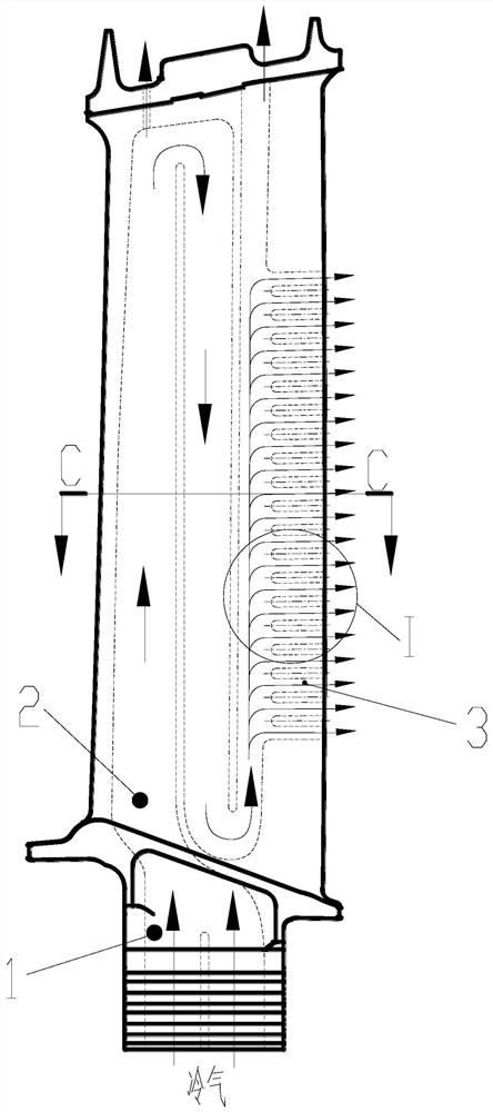
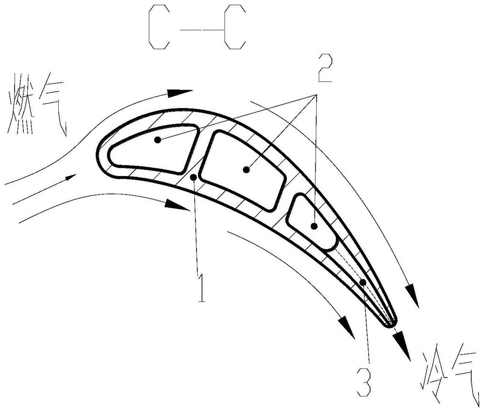
[0031] Please refer to Figure 2, a rosary-style turbine blade trailing edge slit cooling structure, including a hollow turbine blade 1, an inner cavity cold air channel 2 and a trailing edge exhaust slit channel 3;

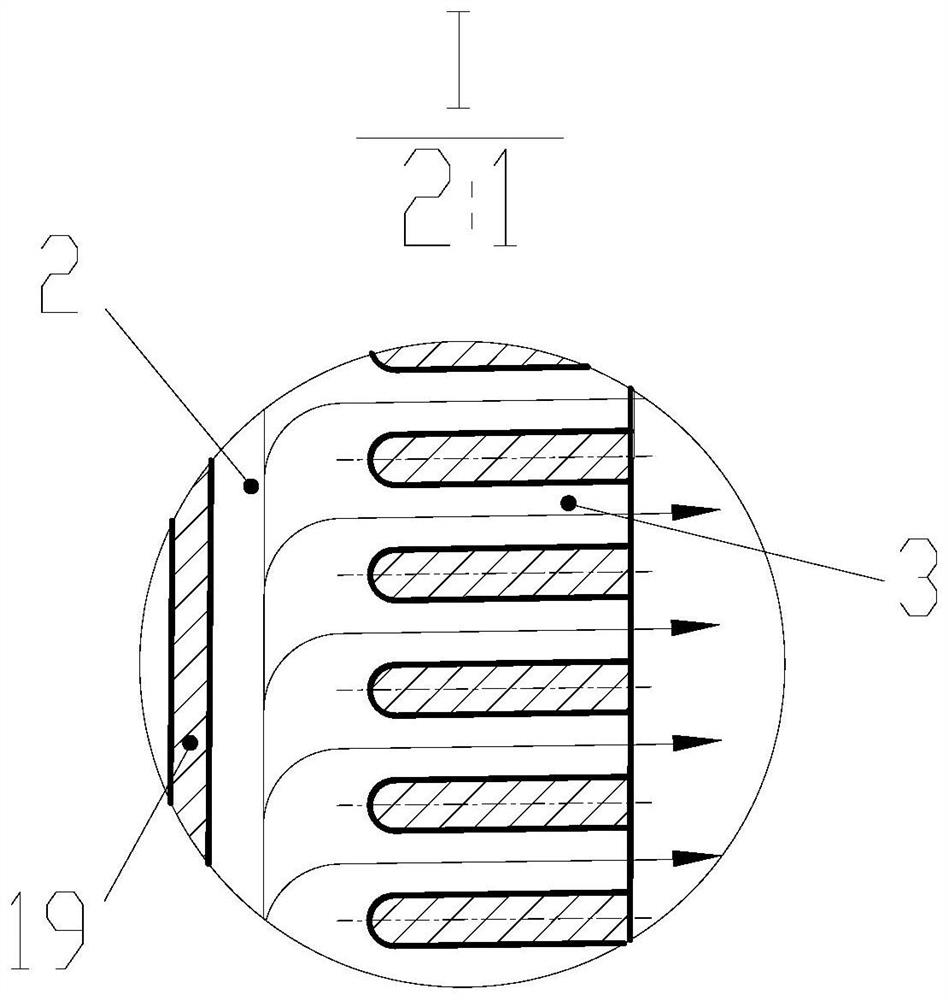
[0032] The interior of the hollow turbine blade 1 is provided with a cold air channel 2 in the cavity, and a plurality of discrete rosary-shaped trailing edge exhaust slit channels 3 are opened along the chord direction at the trailing edge, and its cross-sectional shape is circular or oval. The area changes continuously and alternately between the maximum value and the minimum value along the central line 4 of the slit channel, forming a rosary-like channel structure. Minor axis radius R of channel section x and major axis radius R y Controlled by the A-type wave curve 8 and the B-type wave curve 9 respectively. Typically, as shown in Figure 2(c), the centerline 4 of the split channel is a horizontal straight line in the front view of the blade, the channel inc...

Embodiment 2

[0034] Please refer to Figure 2, a rosary-style turbine blade trailing edge split cooling structure, including a hollow turbine blade 1, an inner cavity cold air passage 2 and a trailing edge exhaust split passage;

[0035] The interior of the hollow turbine blade 1 is provided with a cold air channel 2 in the inner cavity, and a plurality of discrete rosary-shaped trailing edge exhaust slit channels 3 are opened along the chord direction at the trailing edge, and its cross-sectional shape is circular or elliptical. The area changes continuously and alternately between the maximum value and the minimum value along the central line 4 of the slit channel, forming a rosary-like channel structure. Minor axis radius R of channel section x and major axis radius R y Controlled by the A-type wave curve 8 and the B-type wave curve 9 respectively. Typically, such as Figure 4 As shown, the center line 4 of the splitting channel is an inclined straight line in the front view of the bla...


PUM


Abstract

The invention belongs to the technical field of aero-engine turbine cooling, and relates to a rosary-type turbine blade trailing edge slit cooling structure. The cooling structure includes a hollow turbine blade, an inner cavity cold air channel and a trailing edge exhaust slit channel. The hollow turbine blade is provided with an inner cavity cold air channel for low-temperature cooling gas to flow inside the blade to cool the blade. The trailing edge of the hollow turbine blade has a plurality of discrete rosary-shaped trailing edge exhaust slot channels along the chord direction for cooling air to exit the blade. The rosary-type trailing edge exhaust slit of the present invention has a repeatedly contracted and expanded channel structure, which effectively increases the convective heat exchange area between the cold air and the inner channel of the turbine blade trailing edge, compared with the existing slit structure in the trailing edge. The rosary-type trailing edge exhaust slit of the present invention has a repeatedly contracting and expanding channel structure, which can blow off the boundary layer and inhibit its thickening, thereby enhancing heat exchange.

Description

technical field [0001] The invention belongs to the technical field of aero-engine turbine cooling, and relates to a rosary-type turbine blade trailing edge slit cooling structure. Background technique [0002] For aero-engines and gas turbines, increasing the gas temperature before the turbine can greatly improve the efficiency of the device, but because the ambient temperature of the gas is much higher than the current material's ability to withstand, it causes the cooling problem of the turbine blades. At present, the hollow design is commonly used for turbine blades, and the cooling gas is used to remove heat through the enhanced convection heat transfer inside the blades and form a gas film to cover and isolate the gas heating when exhausting the blades. This is the main solution to the cooling problem of turbine blades. [0003] The trailing edge area of ​​the turbine blade is heated by the gas on both sides of the blade basin and back side at the same time, and it is ...

Claims


Application Information

Patent Timeline
Patent Type & Authority Patents(China)
IPC IPC(8): F01D5/18
CPCF01D5/187
Inventor 孔星傲吕东王楠刘英实康浩
Owner DALIAN UNIV OF TECH
Why Eureka
Try Eureka