
Holographic digital array radar target quantity estimation method and system

A technology of digital array radar and target quantity, applied in radio wave measurement system, neural learning method, character and pattern recognition, etc., can solve the problem of low target quantity estimation accuracy and achieve the effect of accurate quantity

Active Publication Date: 2022-03-01
SICHUAN JIUZHOU ELECTRIC GROUP
View PDF22 Cites 0 Cited by
  • Summary
  • Abstract
  • Description
  • Claims
  • Application Information

AI Technical Summary

Problems solved by technology

[0005] The technical problem to be solved by the present invention is: the estimation accuracy of the target quantity in the existing method is low, in order to improve the accuracy rate of target quantity estimation in the holographic digital array radar target detection, the present invention provides the holographic digital array radar target which solves the above-mentioned problems Quantity estimation method and system

Method used


Image

  • Holographic digital array radar target quantity estimation method and system
  • Holographic digital array radar target quantity estimation method and system
  • Holographic digital array radar target quantity estimation method and system

Examples


Embodiment 1

[0063] In order to express the content of the present invention conveniently, the following parameters are firstly defined.

[0064] distance fast time τ

[0065] Azimuth slow time t

[0066] Electromagnetic wave propagation speed c

[0067] Chirp slope K r

[0068] Carrier frequency f 0

[0069] Transmit signal bandwidth B

[0070] Carrier wavelength λ

[0071] Concrete steps of the present invention are as follows.

[0072] Step 1 distance compression

[0073] Suppose the echo signal accumulated for a long time is:

[0074]

[0075] The above four items are recorded as range envelope, azimuth envelope, transmit signal phase and Doppler modulation item respectively.

[0076] The distance compression process is expressed as:

[0077] the s rc (τ,t)=IFFT(s(f τ ,t)H(f τ )) (2)

[0078] where H(f τ ) is the response function of the reference function, s(f τ ,t) is the Fourier transform of the echo in the fast time domain. Substituting formula (1) into formula...

Embodiment 2

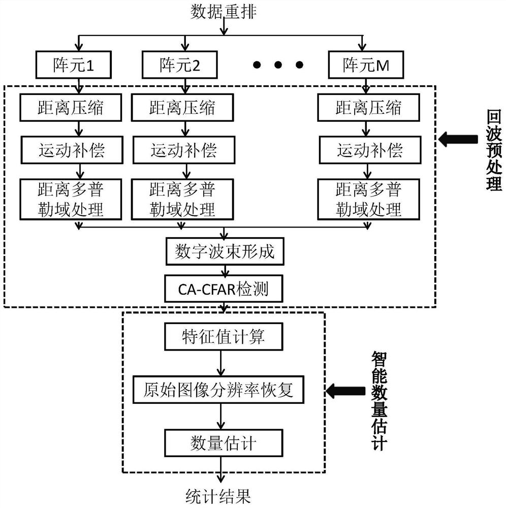
[0106] Such as figure 1 Shown for the specific process of the present invention.

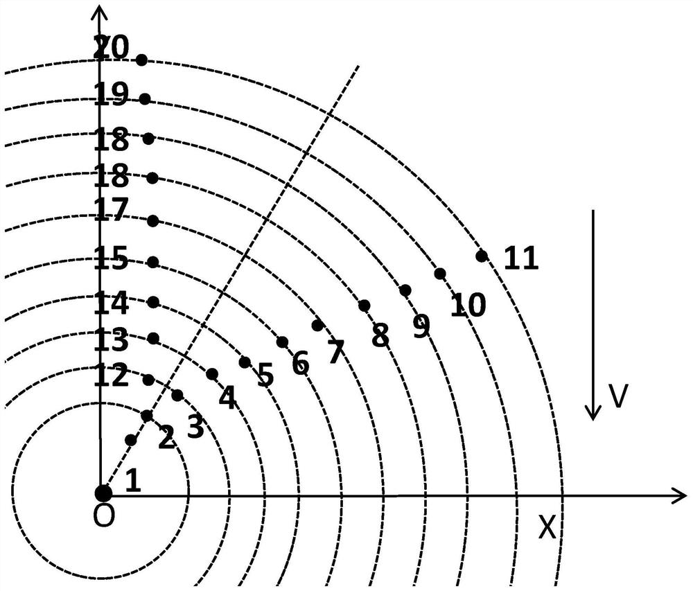
[0107] Taking the radar platform as the coordinate origin, establish as figure 2 The geometry shown. A total of 20 targets are set in the scene, moving along the Y axis at the same speed V=30m / s. The initial angle corresponding to target 1 (the angle offset from the Y axis) θ 1 =12°, the corresponding initial slope distance is R 1 =10000m, the initial angle corresponding to target 2 (the angle offset from the Y axis) θ 2 =12°, the corresponding initial slope distance is R 2 =10010m. The distance between targets 3 and 12 is 10m, and the longitudinal distance corresponding to targets 1 and 2 is 10m. From this calculation, the angle corresponding to targets 3 and 12 is θ 3 =12.0826°,θ 12 =11.9714°, the angular interval between the two is 0.0572°. Targets 4-20 are all incremented at a horizontal and vertical interval of 10m.

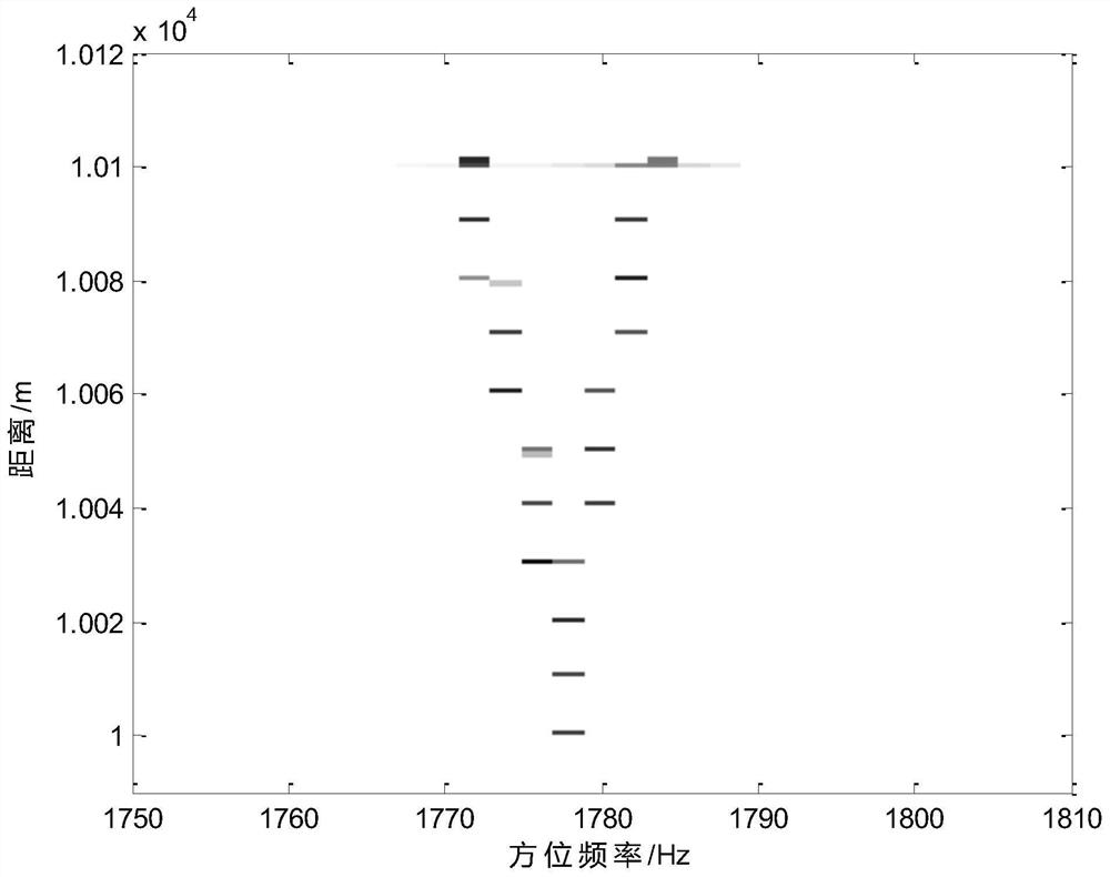
[0108] Based on the matlab platform, according to the above ge...


PUM


Abstract

The invention discloses a method and system for estimating the number of targets of a holographic digital array radar, relates to the field of estimating the number of targets detected by a holographic digital array radar, and solves the problem of low accuracy of estimating the number of targets in the existing method. The present invention is mainly divided into two major steps, echo preprocessing and intelligent quantity estimation, and the specific steps of echo preprocessing are: range compression, motion compensation, range-Doppler processing, target detection; the specific steps of intelligent quantity estimation are: : Initial feature map computation, original image resolution restoration, quantity estimation. The invention uses the staring characteristics of the holographic digital array radar to increase the coherent accumulation time and improve the detection ability of small and weak targets in the background of strong clutter to achieve high resolution of targets in the range-Doppler domain. On this basis, combined with the deep neural network, by segmenting the range-Doppler domain pixels, counting the number of segmented pixel categories and finally completing the estimation of the target number.

Description

technical field [0001] The invention relates to the field of target quantity estimation under holographic digital array radar detection, in particular to a method and system for holographic digital array radar target quantity estimation. Background technique [0002] Estimation of the number of targets is an important application aspect in the detection of holographic digital array radar. It integrates holographic digital array radar and deep neural network, and utilizes the high resolution of targets in the range-Doppler domain brought about by the long-term accumulation of holographic digital array radar. Feature extraction and pixel segmentation of features and deep neural networks to complete target intelligence and high-precision quantity estimation. Through the intelligent estimation of the number of targets based on the holographic digital array radar, the high-resolution and high-precision number estimation of the measured target in a strong clutter environment can b...

Claims


Application Information

Patent Timeline
Patent Type & Authority Patents(China)
IPC IPC(8): G01S7/41G01S13/88G06F17/14G06K9/62G06N3/04G06N3/08G06V10/764G06V10/82
CPCG01S7/414G01S7/417G01S7/418G01S13/88G06F17/14G06N3/08G06N3/045G06F18/24
Inventor 李云莉蒋文李胜军叶祥龙王正伟刘志刚
Owner SICHUAN JIUZHOU ELECTRIC GROUP
Learn More