Optical light splitting device for receiving double wavebands through common window and application thereof

A spectroscopic device and dual-band technology, applied in the field of optics, can solve the problems of large volume, heavy weight, incompatibility, non-portability, lightweight, etc., and achieve the effect of small size, strong adaptability, and light weight

Pending Publication Date: 2021-01-05
HUBEI HUAZHONG PHOTOELECTRIC SCI & TECH
View PDF9 Cites 3 Cited by
  • Summary
  • Abstract
  • Description
  • Claims
  • Application Information

AI Technical Summary

Problems solved by technology

Traditional camera products and ranging products often have large differences in structure and function. The two have completely different lens structures and optical path systems and are not compatible with each other. Larger obstacle
A simple solution is to directly assemble the traditional camera product and the distance measuring product on the same housing. The two are independent of each other, do not interfere with each other, and perform their respective functions. However, such products are often bulky and heavy. And it does not meet the development trend of portability and lightweight

Method used


Image

  • Optical light splitting device for receiving double wavebands through common window and application thereof
  • Optical light splitting device for receiving double wavebands through common window and application thereof

Examples


Embodiment Construction

[0016] In order to enable those skilled in the art to fully understand the technical solutions and beneficial effects of the present invention, further description will be given below in conjunction with specific examples.

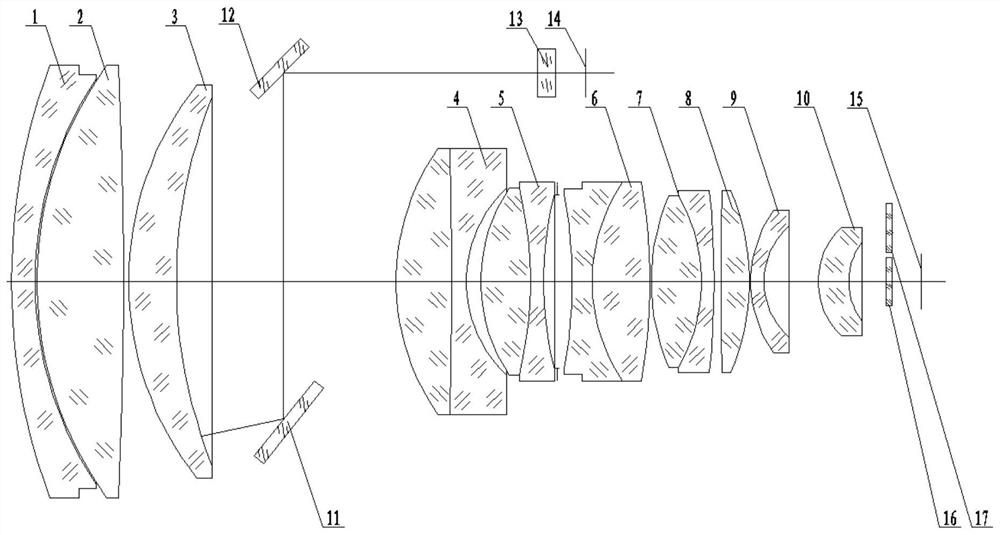
[0017] Such as figure 1 The shown optical spectroscopic device for receiving dual-wave bands through a common window mainly includes two sets of optical path systems, one of which includes a first objective lens 1, an objective second lens 2, an objective third lens 3, and an objective second lens arranged coaxially. One cemented lens 4, objective lens second cemented lens 5, objective lens third cemented lens 6, objective lens fourth cemented lens 7, objective lens twelfth lens 8, objective lens thirteenth lens 9, objective lens fourteenth lens 10, TV detector 15. Visible light filter 16, near-infrared filter 17, and the other path includes the shared objective first lens 1, objective second lens 2, objective third lens 3 and separate mirror I11, mirror I...


PUM


Abstract

The invention relates to an optical light splitting device for receiving double wave bands through a common window and application of the optical light splitting device in camera shooting distance measuring equipment. The device comprises a common lens group, a reflector group, an imaging lens group, an avalanche transistor detector and a television detector, wherein the reflector group is arranged between the common lens group and the imaging lens group, and the common lens group, the imaging lens group and the television detector are arranged along the same optical axis; the two reflectors of the reflector group are parallel to each other and are arranged at two ends of the common lens group at a certain angle with the optical axis; the avalanche transistor detector is over against the light emitting surface of one reflector; the external incident main light penetrates through the shared lens group and the imaging lens group and then enters the television detector to be imaged, so the photographing or camera shooting function is achieved. And after penetrating through the shared lens group, other incident light rays from the outside are reflected to the avalanche transistor detector by the reflector group, so that a distance measuring function is realized. The device has the advantages of being simple in structure, low in manufacturing cost, small in size, light in weight, easy to carry, wide in application range, high in adaptability and the like.

Description

technical field [0001] The invention relates to the field of optical technology, in particular to an optical splitting device for receiving dual-wave bands through a common window and an application thereof. Background technique [0002] With the advancement of technology, multi-functional camera products have higher and higher requirements on function and integration, and multi-functional integrated miniaturized devices play an increasingly important role in practical applications. Traditional camera products and ranging products often have large differences in structure and function. The two have completely different lens structures and optical path systems and are not compatible with each other. Larger obstacle. A simple solution is to directly assemble the traditional camera product and the distance measuring product on the same housing. The two are independent of each other, do not interfere with each other, and perform their respective functions. However, such product...

Claims


Application Information

Patent Timeline
Patent Type & Authority Applications(China)
IPC IPC(8): G02B13/00G02B13/14G01B9/00
CPCG02B13/0065G02B13/006G02B13/0055G02B13/008G02B13/14G01B9/00
Inventor 鲜伟朱国强常大英张俊峰魏文彬高东海方勇强
Owner HUBEI HUAZHONG PHOTOELECTRIC SCI & TECH
Why Eureka
Try Eureka