
Step-by-step multi-threshold voltage unit distribution method based on time sequence margin and time sequence path

A multi-threshold voltage, timing margin technology, applied in the direction of electrical digital data processing, special data processing applications, instruments, etc., can solve the problems of circuit timing not meeting the requirements, circuit power consumption not being optimally optimized, etc., to achieve optimization Good effect, time-saving replacement effect

Active Publication Date: 2021-01-05
ZHEJIANG UNIV
View PDF3 Cites 4 Cited by
  • Summary
  • Abstract
  • Description
  • Claims
  • Application Information

AI Technical Summary

Problems solved by technology

[0004] The multi-threshold voltage allocation method is a hot research issue. Improper allocation of high-threshold voltage units will lead to unsatisfactory timing of the circuit, and improper allocation of low-threshold voltage units will result in the power consumption of the circuit not being optimally optimized.

Method used


Image

  • Step-by-step multi-threshold voltage unit distribution method based on time sequence margin and time sequence path
  • Step-by-step multi-threshold voltage unit distribution method based on time sequence margin and time sequence path
  • Step-by-step multi-threshold voltage unit distribution method based on time sequence margin and time sequence path

Examples


Embodiment Construction

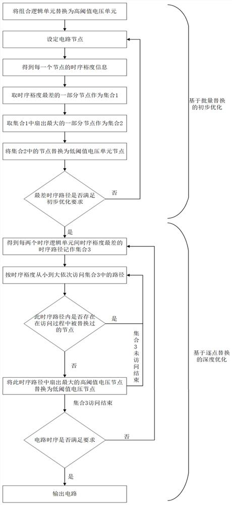
[0027] combine figure 1 , the specific embodiment of the present invention includes two steps of preliminary optimization based on batch replacement and depth optimization based on point-by-point replacement:

[0028] 1) Preliminary optimization based on batch replacement

[0029] Step 1: Read in the circuit netlist and design constraints as input, and convert all combinational logic cells in the circuit into high-threshold voltage cells. Then the combinational logic unit is used as the circuit node of the first round of traversal. Get the timing margin WS of the worst timing path, and set the parameter γ, and use the values ​​of WS and γ as the basis for judging iterations in the preliminary optimization process. The parameters α, β for step 3 are then set. Among them, the values ​​of α, β, γ are fixed values ​​in the iterative process, and 0<α, β, γ<1. α represents the proportion of the selected node with the worst timing margin among the object nodes. β represents the ...


PUM


Abstract

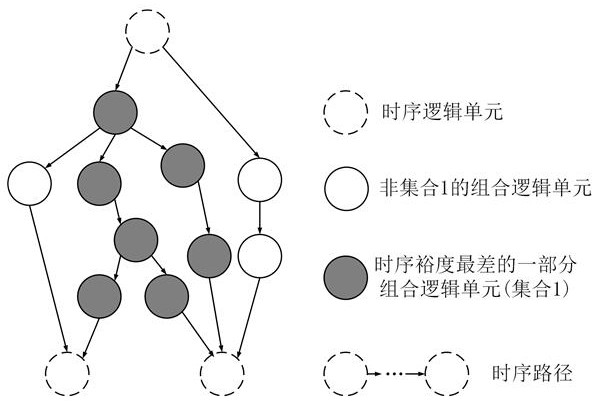
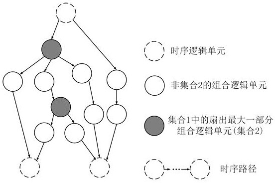
The invention discloses a step-by-step multi-threshold voltage unit distribution method based on unit time sequence margin and a unit time sequence path, and belongs to the technical field of low power consumption of integrated circuit design. The method comprises two steps, namely, preliminary optimization based on batch replacement and deep optimization based on point-by-point replacement. According to the preliminary optimization based on batch replacement, the part, with the maximum fan-out, of the part of nodes with the worst time sequence margin in the circuit is replaced with a low threshold voltage unit in batch, and multiple rounds of iteration are carried out. According to deep optimization based on point-by-point replacement, a unit in each violated time sequence path in each round of replacement circuit is optimized, and iteration is carried out until the circuit time sequence meets the requirement. According to the method, nodes needing to be traversed in depth optimization are effectively reduced through preliminary optimization based on batch replacement, and then it is ensured that the circuit time sequence meets the requirement through depth optimization based on point-by-point replacement.

Description

technical field [0001] The invention belongs to the technical field of low power consumption of integrated circuit design, in particular to the technical field of multi-threshold voltage distribution in low power consumption design of integrated circuits. Background technique [0002] With the continuous shrinking of the process size of integrated circuits and the development of integrated circuit technology to the nanometer size, the clock frequency and integration of chips are constantly improving. At this time, speed is no longer the only goal that needs to be considered in IC design, and the impact of power consumption is becoming more and more significant. Integrated circuit power consumption is divided into dynamic power consumption and static power consumption. In the process of continuous development of integrated circuit technology nodes, the impact of static power consumption is also increasing. [0003] Multi-threshold voltage technology is an effective method to...

Claims


Application Information

Patent Timeline
Patent Type & Authority Applications(China)
IPC IPC(8): G06F30/3315
CPCG06F30/3315G06F2119/06Y02D10/00
Inventor 黄凯李鹏李立浧习伟曾祥君尹项根朱示特郑丹丹
Owner ZHEJIANG UNIV
Learn More