Oil seal structure and oil seal method of cooling transformer

A transformer and oil seal technology, applied in transformer/inductor cooling and other directions, can solve the problems of turbulent flow cost, fast cooling oil flow rate, etc., and achieve the effects of low manufacturing cost, stable oil flow rate and complicated welding process

Active Publication Date: 2021-01-05
常州西电变压器有限责任公司 +1
View PDF11 Cites 0 Cited by
  • Summary
  • Abstract
  • Description
  • Claims
  • Application Information

AI Technical Summary

Problems solved by technology

[0003] In order to solve the problems existing in the prior art, the present invention provides an oil seal structure and an oil seal method for a cooling transformer, which solves the problem t...

Method used


Image

  • Oil seal structure and oil seal method of cooling transformer
  • Oil seal structure and oil seal method of cooling transformer
  • Oil seal structure and oil seal method of cooling transformer

Examples


Embodiment Construction

[0026] The present invention will be further described below in conjunction with the accompanying drawings and specific embodiments.

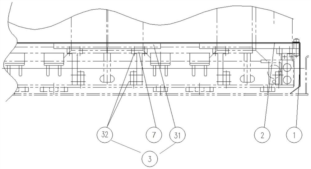
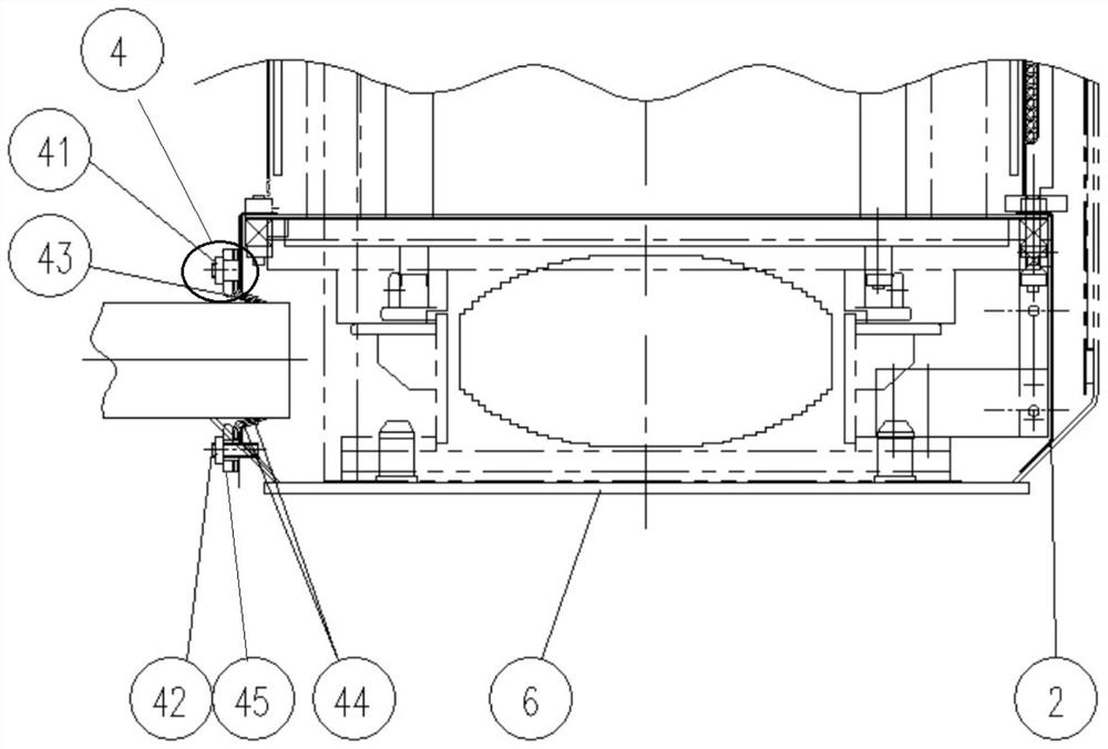
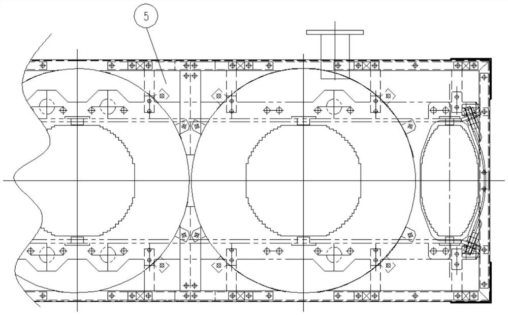
[0027] Such as figure 1 and figure 2 and image 3 As shown, the present invention provides a cooling transformer oil seal structure, including an upper cover 5, the upper cover 5 is arranged in the inner cavity of the oil tank of the transformer, and the long sides of the upper cover 5 are connected with long One end of the oil seal cardboard 2 on the shaft side, the other end of the oil seal cardboard 2 on the long axis side is in contact with the inner wall 6 of the bottom of the fuel tank, and one end of the oil seal cardboard 1 on the short axis side is connected to the broad side of the upper cover plate 5 , the The other end of the oil seal cardboard 1 on the short axis side is in contact with the inner wall 6 at the bottom of the oil tank, and the oil seal cardboard 2 on the long axis side, the oil seal cardboard 1 on the short axis s...


PUM


Abstract

The invention relates to an oil seal structure and an oil seal method of a cooling transformer; the structure comprises an upper cover plate, the upper cover plate is arranged in an inner cavity of anoil tank of the transformer, the long edge of the plate face of the upper cover plate is connected with one end of a long shaft side oil seal paper plate, and the other end of the long shaft side oilseal paper plate makes contact with the inner wall of the bottom of the oil tank; one end of a short shaft side oil seal paper board is connected to the wide edge of the board face of the upper coverplate, the other end of the short shaft side oil seal paper board makes contact with the inner wall of the bottom of the oil tank, and a cavity of an oil seal structure is defined by the long shaft side oil seal paper plate, the short shaft side oil seal paper plate, the upper cover plate and the inner wall of the bottom of the oil tank of the transformer. The other end of the long shaft side oilseal paper plate and the other end of the short shaft side oil seal paper plate are bent towards an inner cavity of the cavity of the oil seal structure, and the upper cover plate is connected with the inner wall of the bottom of the oil tank through a supporting piece. The invention is low in manufacturing cost, the cavity of the oil seal structure is telescopic, and it is guaranteed that the flow speed of oil entering the coil is stable.

Description

technical field [0001] The invention belongs to the technical field of transformer process manufacturing, in particular to an oil seal structure and an oil seal method for cooling a transformer. Background technique [0002] The oil seal structure of the cooling transformer can quickly take away the heat generated by the transformer to ensure the safe and stable operation of the transformer. The conventional oil seal structure is to weld the cavity on the clamp, and then open a hole on the lower pressure plate of the body, and use the oil pump to transfer the cooling The oil is injected into the cavity, and the cold oil reaches various parts of the transformer coil through the cavity and the pressure plate hole. However, due to the complicated welding process and high cost of this structure, and if the thickness of the lower pressure plate is too small, the flow rate of the injected cold oil into the coil If it is too fast, turbulent flow will appear, which will pose a poten...

Claims


Application Information

Patent Timeline
IPC IPC(8): H01F27/12H01F27/14
CPCH01F27/12H01F27/14
Inventor 李子兴吴国良曹敬宝孙旿
Owner 常州西电变压器有限责任公司
Why Eureka
Try Eureka