
Radio frequency cancellation method based on optical true time delay network

An optical true delay and radio frequency technology, which is applied in the fields of radar detection, radio frequency communication, and microwave photonics, can solve problems such as signal distortion and limit the real-time performance of broadband interference signals, achieve large tuning accuracy, solve radio frequency cancellation problems, and improve The effect of frequency range

Inactive Publication Date: 2021-01-05
SOUTHWEST JIAOTONG UNIV
View PDF2 Cites 4 Cited by
  • Summary
  • Abstract
  • Description
  • Claims
  • Application Information

AI Technical Summary

Problems solved by technology

However, when the interference signal power is high, it will directly saturate the front-end amplifier of the receiver and cause signal distortion; in addition, as the frequency bands used in electronic reconnaissance and full-duplex wireless communication are getting higher and higher, the response of digital signal processing technology The rate also limits the real-time performance of processing broadband interference signals

Method used


Image

  • Radio frequency cancellation method based on optical true time delay network
  • Radio frequency cancellation method based on optical true time delay network
  • Radio frequency cancellation method based on optical true time delay network

Examples


Embodiment Construction

[0019] The present invention will be described in further detail below in conjunction with the accompanying drawings and specific implementation methods.

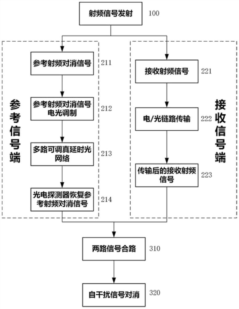
[0020] A radio frequency cancellation method based on optical true delay network of the present invention such as figure 1 shown, including the following steps:

[0021] 1. The RF signal transmitting end divides the transmitting RF signal (100) into a transmitting RF signal and a reference RF cancellation signal (211), wherein the transmitting RF signal is sent, and the reference RF signal (211) is sent to the reference signal terminal for processing.

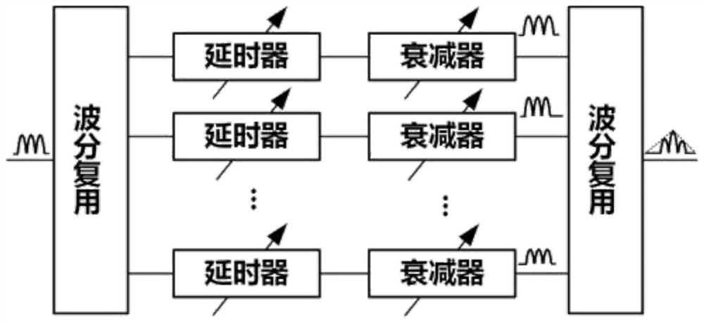
[0022] 2. Use an undimmed signal with multiple frequency components as a light source to generate different channels that can be used by the delay network. Using a multi-wavelength laser as a light source, the output optical signal can be expressed as:

[0023]

[0024] Among them, A k is the amplitude of the kth wavelength, ω k is the angular frequency of the kth wav...


PUM


Abstract

The invention discloses a radio frequency cancellation method based on an optical true time delay network, and the method specifically comprises the steps: dividing a transmitted radio frequency signal into two paths: modulating a reference radio frequency cancellation signal to an unmodulated signal with multiple frequency components at a reference signal end, dividing the reference radio frequency cancellation signal into multiple paths of modulated optical signals through a wavelength division multiplexer, sending the signals to a multi-channel adjustable true delay optical network for delay amount and attenuation amount adjustment, and sending the combined output signals to a photoelectric detector to recover reference radio frequency cancellation signals; at a signal receiving end, transmitting the received radio frequency signal through an electric or optical link and outputting the received radio frequency signal; and finally, combining and subtracting the reference radio frequency cancellation signal recovered by the reference signal end from the received radio frequency signal, and outputting two paths of combined signals to obtain the received radio frequency signal afterthe reference radio frequency cancellation signal is eliminated. According to the invention, a time delay technology with a larger adjustment range and tuning precision can be provided, interferencesignals with agile characteristics can be responded and processed more quickly, and the method is of great significance for solving the problem of radio frequency cancellation of a receiving end.

Description

technical field [0001] The invention belongs to the fields of microwave photonics, radio frequency communication and radar detection, and in particular relates to a radio frequency cancellation method based on an optical true delay network. Background technique [0002] Under complex electromagnetic environment conditions, the interference signals faced by the front end of the RF receiver generally have the characteristics of agility, wide spectrum, and strong power. The existence of interference signals will cause the receiver to fail to measure and process the signals normally. In general, the interference signal can be eliminated after digital sampling. However, when the interference signal power is high, it will directly saturate the front-end amplifier of the receiver and cause signal distortion; in addition, as the frequency bands used in electronic reconnaissance and full-duplex wireless communication are getting higher and higher, the response of digital signal proc...

Claims


Application Information

Patent Timeline
IPC IPC(8): H04B1/525H04B1/10H04B1/12H04B10/40
CPCH04B1/1081H04B1/123H04B1/525H04B10/40
Inventor 叶佳余骁罗健威闫连山潘炜
Owner SOUTHWEST JIAOTONG UNIV
Learn More