
Fire extinguishing system for indoor transformer and control method thereof

A technology of fire protection system and transformer, which is applied in fire rescue and other directions, and can solve problems such as threats to the safety of power supply personnel, water mist cooling, insulation, limited suffocation effect, and low reliability

Active Publication Date: 2021-01-08
JIANGSU ELECTRIC POWER CO +1
View PDF6 Cites 4 Cited by
  • Summary
  • Abstract
  • Description
  • Claims
  • Application Information

AI Technical Summary

Problems solved by technology

Once the transformer fails, it is likely to cause an electrical fire accident, which seriously threatens the safety of power supply personnel
In response to this situation, there is currently an indoor water mist fire-fighting device that starts fire extinguishing by spraying water mist from multiple angles to the transformer space configured indoors. However, this method requires the installation of large-capacity water storage tanks, water mist pumps, control The structure is relatively complicated, and the cooling, insulation, and suffocation effects of fine water mist are limited, so it cannot play a good role in fire extinguishing; moreover, general indoor water mist fire fighting devices often only pass the signal of temperature Control its action, the reliability is low, and it will also affect the fire fighting effect

Method used


Image

  • Fire extinguishing system for indoor transformer and control method thereof
  • Fire extinguishing system for indoor transformer and control method thereof
  • Fire extinguishing system for indoor transformer and control method thereof

Examples


Embodiment Construction

[0027] The present invention is described below based on examples, but the present invention is not limited to these examples. In the following detailed description of the present invention, some specific details are described in detail, and in order to avoid obscuring the essence of the present invention, known methods, procedures, procedures, and components are not described in detail.

[0028] Additionally, those of ordinary skill in the art will appreciate that the drawings provided herein are for illustrative purposes and are not necessarily drawn to scale.

[0029] Unless the context clearly requires, throughout the specification and claims, "comprises", "comprises" and similar words should be interpreted in an inclusive sense rather than an exclusive or exhaustive meaning; that is, "including but not limited to" meaning.

[0030] In the description of the present invention, it should be understood that the terms "first", "second" and so on are used for descriptive purp...


PUM


Abstract

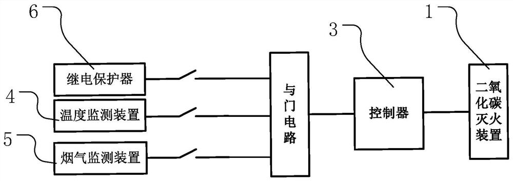
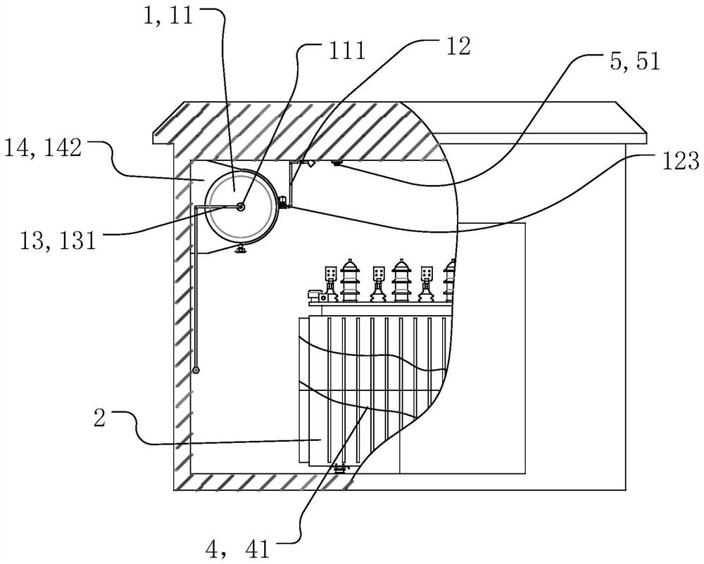
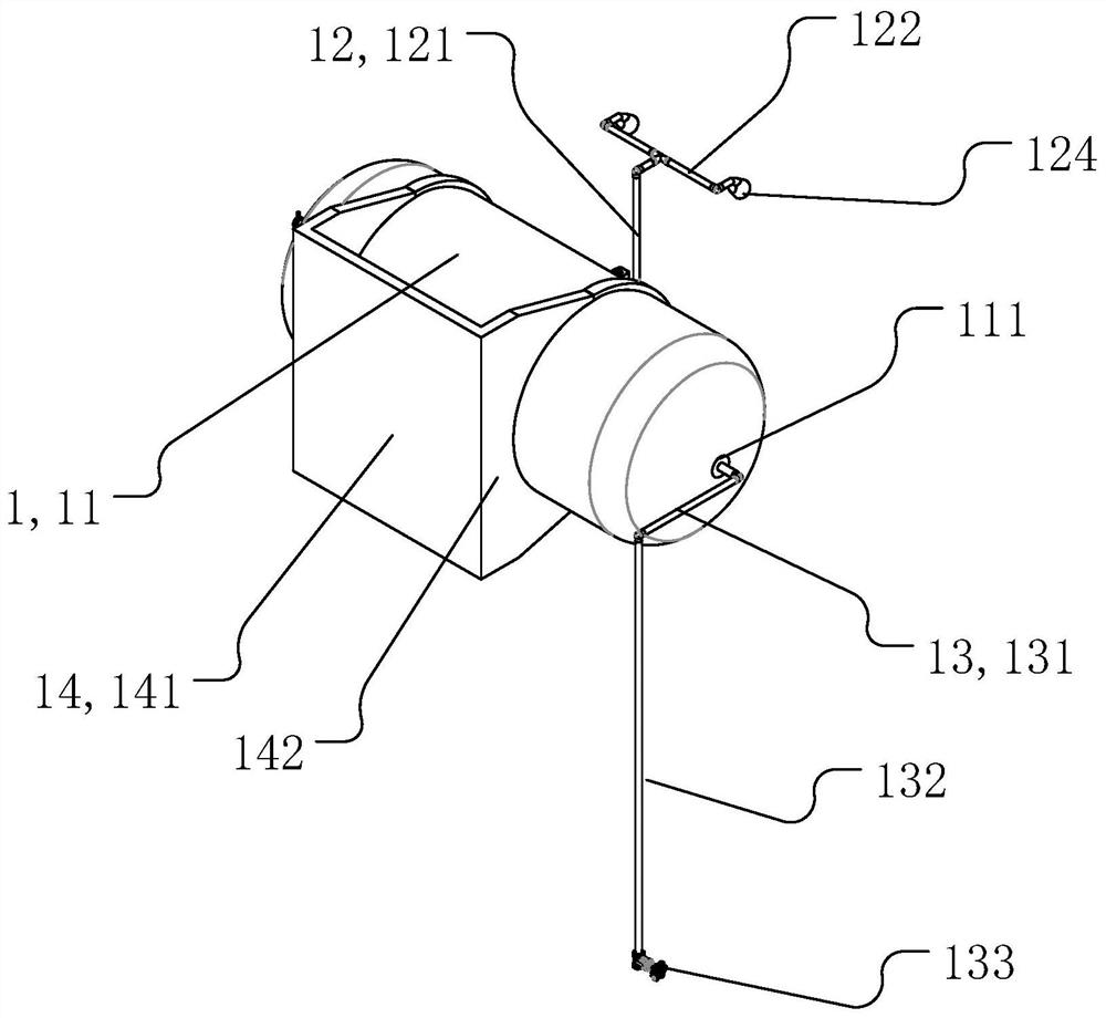
The invention provides a fire extinguishing system for an indoor transformer and a control method thereof. The transformer comprises a relay protection pipe. The fire extinguishing system for the indoor transformer comprises a controller, a carbon dioxide fire extinguishing device, a temperature monitoring device and a flue gas monitoring device. The carbon dioxide fire extinguishing device comprises a liquid storage part for storing liquid carbon dioxide, a spraying assembly mounted on the liquid storage part and an electric control switch for controlling a spray port of the spraying assemblyto open and close. The temperature monitoring device is used for detecting temperature of the transformer, a flue gas detection device is used for monitoring flue gas concentration indoors, and the controller is electrically connected to a relay protector, the temperature monitoring device and the flue gas monitoring device. The controller is used for receiving signals sent by the relay protector, the temperature monitoring device and the flue gas monitoring device and controlling the electric control switch to open and close according to the signals. The fire extinguishing system for the indoor transformer can solve problems in the prior art and is simple in structure and better in fire extinguishing effect.

Description

technical field [0001] The invention relates to the technical field of transformer fire protection, in particular to an indoor transformer fire protection system and a control method thereof. Background technique [0002] Power safety has always been a key issue in the operation of the power grid. Therefore, power equipment will have corresponding relay protectors to protect the corresponding power equipment during operation, that is, identify power by detecting electrical or non-electrical parameters such as current and voltage of power equipment. The fault state of the equipment, and the action is to remove the faulty equipment from the grid. For example, when the transformer, which is the core equipment in the substation, fails, the relay protector will operate to trip the switches on each side (usually three sides) of the transformer to isolate the faulty transformer. [0003] With the development of the power grid and the improvement of equipment, the transformers in m...

Claims


Application Information

Patent Timeline
Patent Type & Authority Applications(China)
IPC IPC(8): A62C3/16A62C37/40A62C99/00
CPCA62C3/16A62C37/40A62C99/0027
Inventor 陈晓夏星郭建松李茹周姣容陈斌
Owner JIANGSU ELECTRIC POWER CO
Features
  • Generate Ideas
  • Intellectual Property
  • Life Sciences
  • Materials
  • Tech Scout
  • Unparalleled Data Quality
  • Higher Quality Content
  • 60% Fewer Hallucinations
Learn More