Blanking equipment and method for machining transformer iron core oil groove
A technology for transformers and oil tanks, which is applied in metal processing equipment, inductor/transformer/magnet manufacturing, and push-out equipment. It can solve the problems of less oil tank processing equipment, affecting the performance of transformers, and unable to adjust the size, so as to ensure parallelism and position adjustment. Convenience, performance-enhancing effects
- Summary
- Abstract
- Description
- Claims
- Application Information
AI Technical Summary
Problems solved by technology
Method used
Image
Examples
specific Embodiment approach
[0034] It should be noted that the structures, proportions, sizes, etc. shown in this specification are only used to cooperate with the content disclosed in the specification for the understanding and reading of those familiar with this technology, and are not used to limit the conditions for the implementation of the present invention , any modification of structure, change of proportional relationship or adjustment of size shall still fall within the scope covered by the technical content disclosed in the present invention without affecting the effect and purpose of the present invention. .
[0035] At the same time, terms such as "upper", "lower", "left", "right", "middle" and "one" quoted in this specification are only for the convenience of description and are not used to limit this specification. The practicable scope of the invention and the change or adjustment of its relative relationship shall also be regarded as the practicable scope of the present invention without...
Embodiment 1
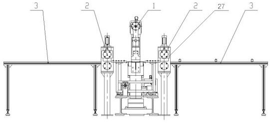
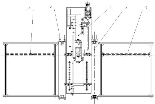
[0037] Such as Figure 1~2 As shown, the present invention discloses a punching equipment for processing transformer iron core oil grooves, including a punching punch 1, a pulling feeding device 2, a loading platform 3 and a control assembly, wherein there are two pulling feeding devices 2, and the The two pulling and feeding devices 2 are respectively arranged on the feeding side and the discharging side of the punching machine 1, and there are two loading platforms 3, wherein the two loading platforms 3 are respectively arranged on the two pulling and feeding devices 2 away from the punching machine. One side of the groove punching machine 1, the working surface of the punching groove punching machine 1, the working surface of the pulling feeding device 2 and the upper end surface of the loading platform 3 are on the same horizontal plane, wherein the punching groove punching machine 1 and the pulling feeding device 2 are respectively connected with the control The component...
Embodiment 2
[0039] Such as Figure 1~2 As shown, preferably, the loading platform 3 is installed on the outermost side of the punching equipment, and both the feeding side and the discharging side are installed; the pulling feeding device 2 is placed next to the loading platform 3, and the feeding side is installed as a feeding device. The discharge side is installed as a pulling device, and there is no connection between the pulling and feeding device 2 and the loading platform 3, which are fixed through the foundation; the punching machine 1 is installed in the center of the equipment, and is used to complete the punching of the oil tank, and the punching machine 1 There is no fixed connection with the pulling and feeding device 2, and the relative position is adjusted through the foundation position, so that the working surface of the punching punch 1, the working surface of the pulling and feeding device 2 and the upper end surface of the loading platform 3 are on the same level.
[0...
PUM
 Abstract
Description
Claims
Application Information
 - R&D
- Intellectual Property
- Life Sciences
- Materials
- Tech Scout
- Unparalleled Data Quality
- Higher Quality Content
- 60% Fewer Hallucinations
Browse by: Latest US Patents, China's latest patents, Technical Efficacy Thesaurus, Application Domain, Technology Topic, Popular Technical Reports.
© 2025 PatSnap. All rights reserved.Legal|Privacy policy|Modern Slavery Act Transparency Statement|Sitemap|About US| Contact US: help@patsnap.com


