
Laser high-speed cutting equipment and method thereof

A fast cutting and laser technology, used in laser welding equipment, welding/cutting auxiliary equipment, welding equipment, etc., can solve the problems of clamping and fixing not working properly, unfavorable cutting work for users, etc., to facilitate cutting work and ensure smooth progress. Effect

Inactive Publication Date: 2021-01-08
董良印
View PDF9 Cites 0 Cited by
  • Summary
  • Abstract
  • Description
  • Claims
  • Application Information

AI Technical Summary

Problems solved by technology

[0004] The purpose of the present invention is to solve the shortcomings in the prior art, such as: the existing laser cutting device cannot conveniently complete the fixing work of the material to be processed, and the original clamping and fixing can not work normally, which greatly It is not conducive to users to carry out cutting work

Method used


Image

  • Laser high-speed cutting equipment and method thereof
  • Laser high-speed cutting equipment and method thereof
  • Laser high-speed cutting equipment and method thereof

Examples


Embodiment Construction

[0025] The following will clearly and completely describe the technical solutions in the embodiments of the present invention with reference to the accompanying drawings in the embodiments of the present invention. Obviously, the described embodiments are only some, not all, embodiments of the present invention.

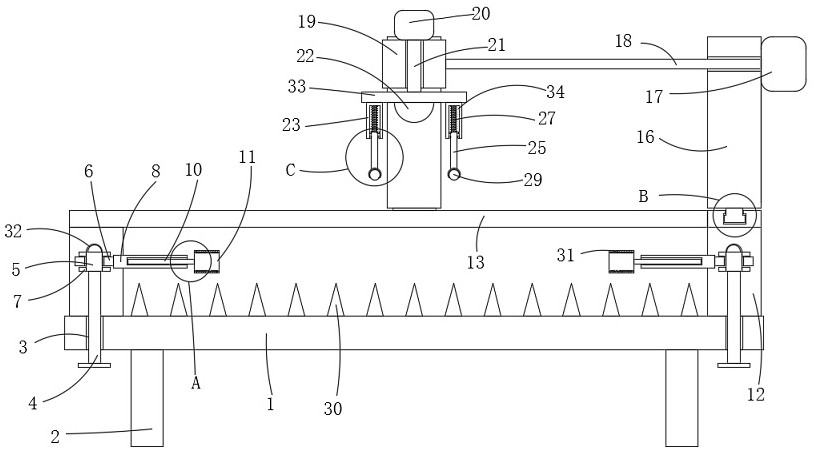
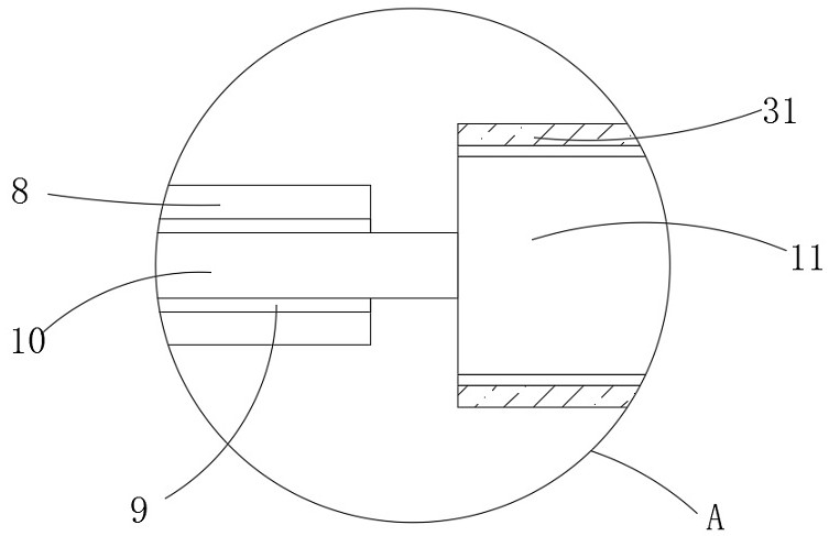
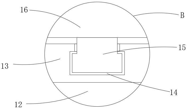
[0026] refer to Figure 1-6 , a laser rapid cutting device, comprising a base 1, a plurality of support blocks 30 arranged at equal intervals are fixedly connected to the side wall of the base 1 away from the feet 2, and the plurality of support blocks 30 are all tapered. A support block 30 that is set in a tapered shape can well complete the supporting work of the material to be cut, so that the material to be cut will not touch the base 1, so that when the user performs laser cutting on the material to be cut, it will not hurt The base 1 greatly guarantees the safety of the device. The lower end surface of the base 1 is fixedly connected with four feet 2 which are ...


PUM


Abstract

The invention discloses laser high-speed cutting equipment which comprises a base, wherein the lower end surface of the base is fixedly connected with four underlaying legs which are arranged in a symmetrical manner; the base is provided with four fixing devices which are arranged in a symmetrical manner; each of the four fixing devices comprises a threaded hole arranged in the base; threaded columns are connected in the threaded holes in a threaded manner; the ends, away from the base, of the threaded columns are fixedly connected with rotating columns; the rotating columns are rotationally connected with circular rings; each of the rotating columns is fixedly connected with two fixing disks which are separately positioned on the two sides of the corresponding circular ring; and the outerwall of one side of each of the circular rings is fixedly connected with a fixing column. The laser high-speed cutting equipment has the beneficial effects of conveniently completing the clamping andfixing work of to-be-machined materials of different sizes, effectively guaranteeing the stability of part of the materials in a machining area, and greatly ensuring the smooth running of the cuttingand machining work carried out by a user.

Description

technical field [0001] The invention relates to the technical field of laser processing, in particular to a laser rapid cutting device. Background technique [0002] In modern industrial production, a large amount of material processing is required, among which laser cutting is a common processing technology. Laser cutting uses high-power-density laser beams to irradiate the cut material, so that the material is quickly heated to the vaporization temperature. Holes are formed by evaporation, and as the beam moves to the material, the holes continuously form narrow slits to complete the cutting of the material, for which a corresponding laser cutting device is required. [0003] When the existing laser cutting device is working, it is often impossible to complete the clamping and fixing work conveniently due to the different sizes of the materials to be processed, which greatly hinders the user from performing stable cutting work, and after the user completes part of the cutt...

Claims


Application Information

Patent Timeline
IPC IPC(8): B23K26/38B23K26/70B23K37/04
CPCB23K26/38B23K26/702B23K37/0443
Inventor 董良印
Owner 董良印
Features
  • Generate Ideas
  • Intellectual Property
  • Life Sciences
  • Materials
  • Tech Scout
  • Unparalleled Data Quality
  • Higher Quality Content
  • 60% Fewer Hallucinations
Learn More