

Silicon wafer overturning and conveying system and method
A technology for conveying systems and silicon wafers, applied to conveyors, conveyor objects, transportation and packaging, etc., can solve problems such as low efficiency, and achieve the effect of improving safety and efficiency
- Summary
- Abstract
- Description
- Claims
- Application Information
AI Technical Summary
Problems solved by technology
Method used
Image

Examples
Embodiment Construction
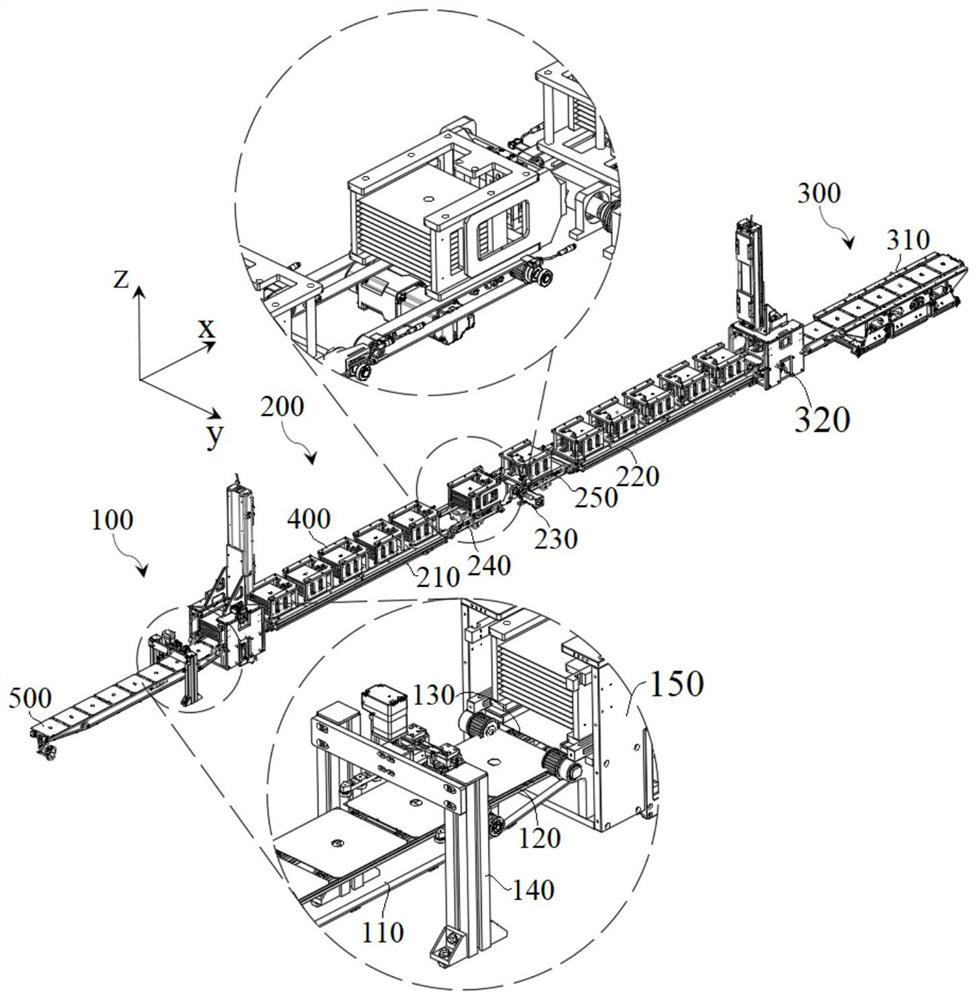
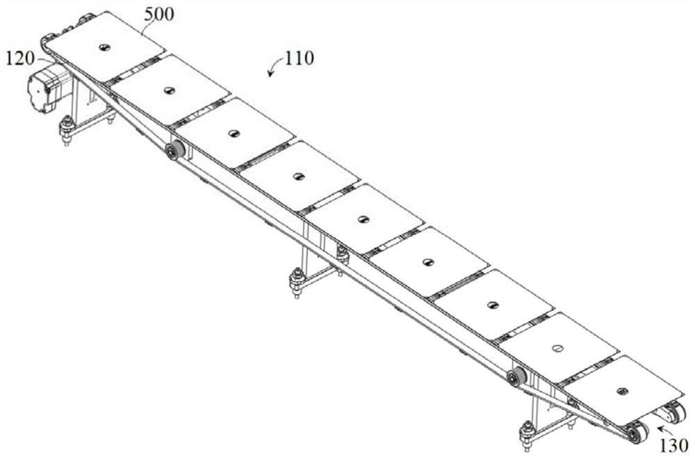
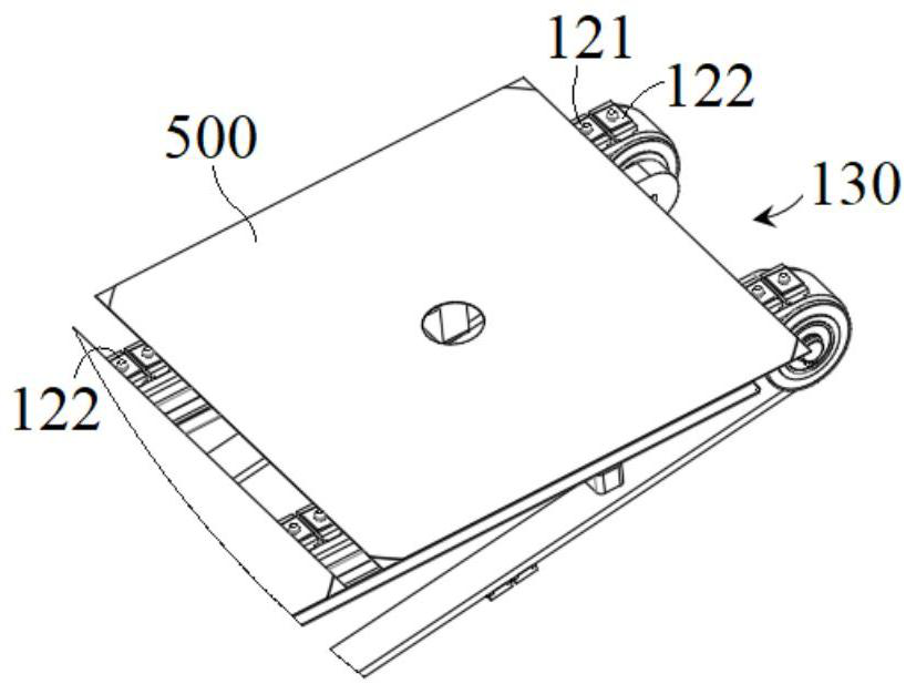
[0049] In order to further understand the content of the present invention, the present invention will be described in detail in conjunction with the accompanying drawings and embodiments.
[0050] The structures, proportions, sizes, etc. shown in the drawings of this specification are only used to cooperate with the content disclosed in the specification, for those who are familiar with this technology to understand and read, and are not used to limit the conditions for the implementation of the present invention. Therefore, Without technical substantive significance, any modification of structure, change of proportional relationship or adjustment of size shall still fall within the technology disclosed in the present invention without affecting the effect and purpose of the present invention. within the scope of the content. At the same time, terms such as "upper", "lower", "left", "right", and "middle" quoted in this specification are only for the convenience of description...
PUM
 Abstract
Description
Claims
Application Information