Permanent magnet synchronous motor position control method based on boundary layer reaching law

A technology of permanent magnet synchronous motor and control method, which is applied in the direction of motor generator control, AC motor control, electronic commutation motor control, etc., and can solve problems such as difficult to obtain satisfactory tracking effect

Active Publication Date: 2021-01-08
ZHEJIANG UNIV OF TECH
View PDF7 Cites 1 Cited by
  • Summary
  • Abstract
  • Description
  • Claims
  • Application Information

AI Technical Summary

Problems solved by technology

[0004] For the permanent magnet synchronous motor dynamic system, although the traditional control can meet the control performance requirements within a certain range, it is difficult to obtain a satisfactory tracking effect due to the strong coupling of the motor system, multi-variable characteristics, and the influence of motor parameter changes.

Method used


Image

  • Permanent magnet synchronous motor position control method based on boundary layer reaching law
  • Permanent magnet synchronous motor position control method based on boundary layer reaching law
  • Permanent magnet synchronous motor position control method based on boundary layer reaching law

Examples


Embodiment Construction

[0084] The present invention will be further described below in conjunction with the accompanying drawings.

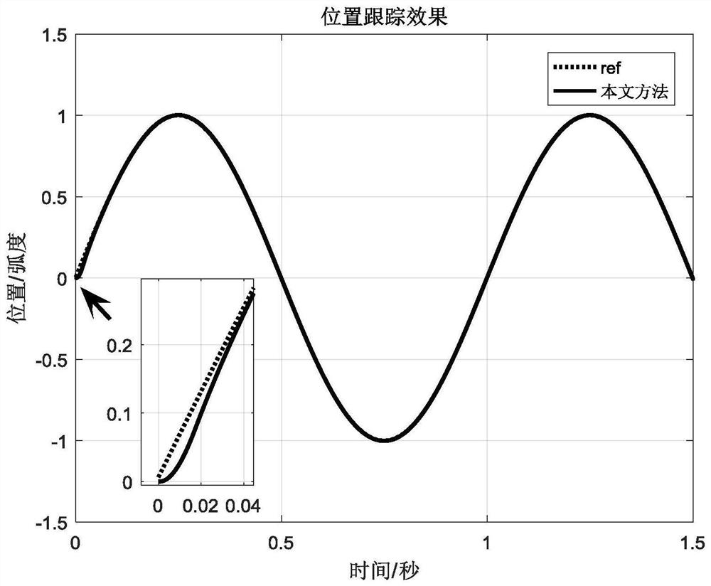
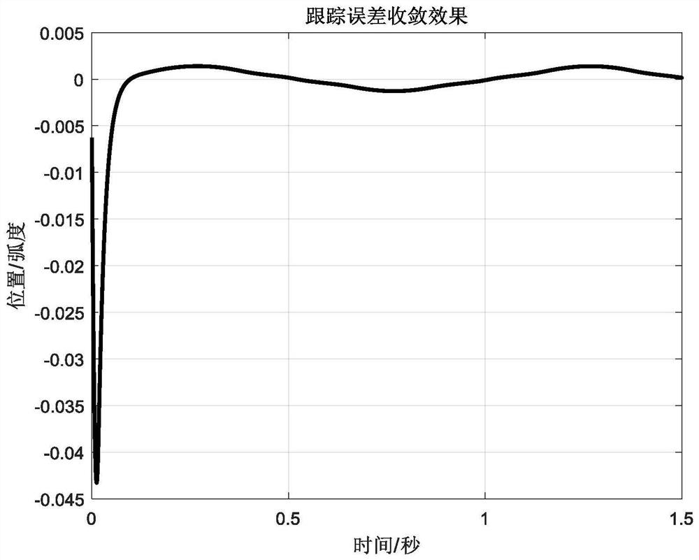
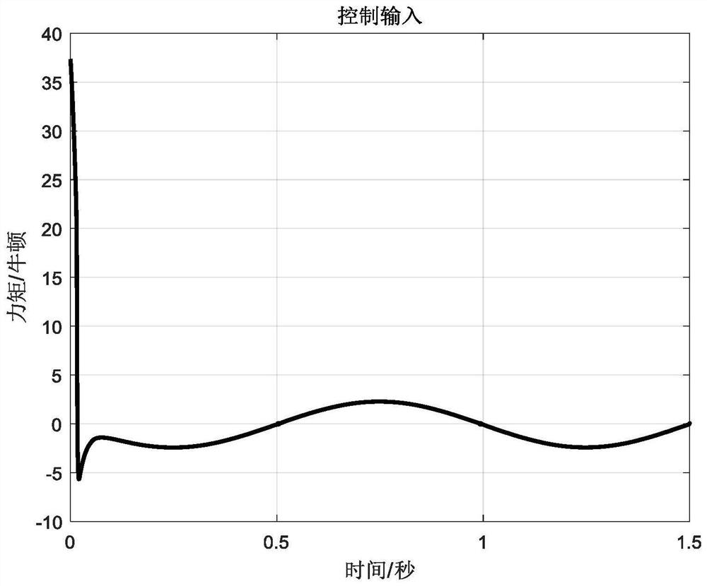
[0085] refer to Figure 1-Figure 5 , a method for position control of permanent magnet synchronous motor based on boundary layer reaching law, comprising the following steps:

[0086] Step 1, the permanent magnet synchronous motor model is:

[0087]

[0088] Among them, θ is the angle of the motor rotor, ω is the electrical angular velocity of the motor rotor, J is the moment of inertia of the motor, n p is a polar logarithm, is the flux linkage between the permanent magnet pole and the stator winding, u is the q-axis current, B is the friction coefficient between the rotor and the load, T l is the load torque;

[0089] make Formula (1) can be simplified as

[0090]

[0091] Among them, the expression of a(t) is:

[0092] a(t)=d+(b-b 0 ) u (3)

[0093] Among them, b 0 is the empirical value of b,

[0094] Step 2, calculate the tracking error of the...


PUM


Abstract

The invention discloses a permanent magnet synchronous motor position control method based on a boundary layer reaching law, and aims at a permanent magnet synchronous motor system with inertia uncertain factors and external disturbance. According to a dynamical system of the permanent magnet synchronous motor, a boundary layer reaching law is designed, and a permanent magnet synchronous motor position control method based on the boundary layer reaching law is designed by adopting a sliding mode control method and combining an adaptive method. The boundary layer reaching law is designed to ensure the rapidity of the system outside the boundary layer, decelerate in the boundary layer and weaken buffeting. Adaptive control is used to handle inertial uncertainty and external disturbances of the system. The invention provides a control method capable of weakening buffeting and effectively inhibiting and compensating inertia uncertainty and external interference of the system, and the finite time convergence characteristic of the system is ensured.

Description

technical field [0001] The invention relates to a method for controlling the position of a permanent magnet synchronous motor based on a boundary layer reaching law, in particular to a method for controlling a permanent magnet synchronous motor system with uncertain factors and external disturbances. Background technique [0002] Permanent magnet synchronous motors use permanent magnets to directly provide excitation so that they have the characteristics of simple structure. With the discovery of permanent magnet materials with good performance and the advancement of motor manufacturing technology, various types of permanent magnet synchronous motors with superior performance have been promoted. develop. In addition to the wider application of permanent magnet synchronous motors, the technology of permanent magnet synchronous motors is also developing continuously, and is constantly developing in the direction of lower prices, high precision, and high torque. In the last ce...

Claims


Application Information

Patent Timeline
Patent Type & Authority Applications(China)
IPC IPC(8): H02P21/00H02P21/14H02P21/18H02P25/022
CPCH02P21/0007H02P21/14H02P21/18H02P25/022
Inventor 陈强曹雅倩吴春
Owner ZHEJIANG UNIV OF TECH
Why Eureka
Try Eureka