
Emergency operating system

A technology of operating system and emergency system, applied in the direction of hoisting device, clockwork mechanism, etc., can solve problems such as accidents, hydraulic system shocks, large displacement of hydraulic motors, etc., to avoid safety accidents and increase back pressure. Effect

Pending Publication Date: 2021-01-12
SOUTH CHINA MARINE MACHINERY
View PDF0 Cites 0 Cited by
  • Summary
  • Abstract
  • Description
  • Claims
  • Application Information

AI Technical Summary

Problems solved by technology

[0004] At present, the emergency operation process of the electric crane is that the crane's line output controlled by the emergency switch is finally connected in parallel to drive the actuator. The emergency switch directly connects the electric proportional pilot valve that needs to be energized for emergency operation with a 24V voltage signal. , during the operation of the mechanism with the emergency switch, since the electric proportional pilot valve of the hydraulic motor is directly connected to the 24V voltage signal, after this voltage signal is added to both ends of the pilot valve, a control current greater than 1A will be generated, so that the hydraulic motor’s The displacement reaches the maximum in an instant, causing a large impact on the hydraulic system. Such an impact will cause the mechanism to move unevenly during the emergency operation, and even cause accidents in serious cases. Due to the existence of such an impact, the existing crane It is difficult for the emergency system to play its due role at critical moments

Method used


Image

  • Emergency operating system
  • Emergency operating system
  • Emergency operating system

Examples


Embodiment Construction

[0044] The present invention will be described in further detail below in conjunction with the accompanying drawings and specific embodiments.

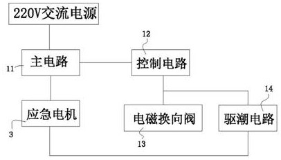
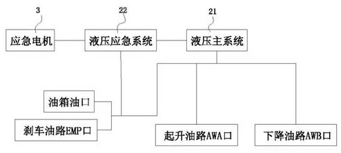
[0045] Such as Figure 1-Figure 10 As shown, an emergency operating system includes a 220V AC power supply and an emergency system, the emergency system is electrically connected to the 220V AC power supply, and the emergency system includes an electric control system, a hydraulic control system and an emergency motor 3 .

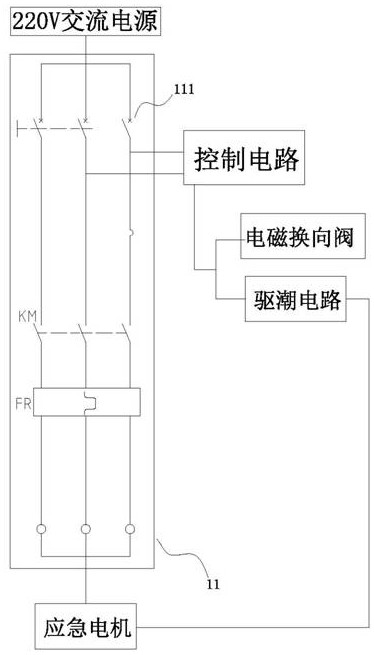
[0046] The electric control system includes a main circuit 11, a control circuit 12, an electromagnetic reversing valve 13 and a tide driving circuit 14. One end of the main circuit 11 is electrically connected to a 220V AC power supply, and the other end is electrically connected to an emergency motor 3, such as image 3 As shown, the main circuit 11 is connected in series with the first manual switch 111, the main contact switch of the relay KM and the main contact of the thermal relay FR, and the control circuit...


PUM


Abstract

The invention provides an emergency operating system. The system comprises a 220V alternating-current power supply and an emergency system, the emergency system is electrically connected with the 220Valternating-current power supply, and the emergency system comprises an electric control system, a hydraulic control system and an emergency motor. The electric control system comprises a main circuit, a control circuit, an electromagnetic reversing valve and a moisture removing circuit, one end of the main circuit is electrically connected with a 220V alternating-current power supply, the otherend of the main circuit is electrically connected with the emergency motor, the control circuit is electrically connected to the main circuit, and the moisture removing circuit is electrically connected to the control circuit in parallel; and the hydraulic control system comprises a hydraulic main system and a hydraulic emergency system. The hydraulic main system comprises a winch, a hydraulic brake, a hydraulic motor, a shuttle valve, a balance valve, a first reversing valve, a second reversing valve, a first ball valve, a lifting oil way AWA port, a descending oil way AWB port, an oil tank oil port and a brake oil way EMP port. The hydraulic emergency system comprises an overflow valve and an electromagnetic reversing valve. The system has the advantages that no voltage transformation isneeded during emergency operation, and the emergency operation is safe and stable.

Description

technical field [0001] The invention relates to the technical field of cranes, in particular to an emergency operating system. Background technique [0002] In the traditional crane winch, when the winch moves, when the brake is released and the hook is raised or lowered, the brake will not be fully opened due to insufficient pressure in the brake hydraulic oil circuit, resulting in brake vibration of the winch. In this way, There is a risk of insufficient pressure in the brake hydraulic oil circuit causing the winch to brake again. Once a sudden brake occurs during the lifting of the hook, it may cause the cargo to be unhooked; The high-pressure oil in the road is unloaded, however, due to the influence of back pressure when the hook lifts or descends the oil circuit to relieve pressure, there will be a certain back pressure at the brake oil inlet, thereby reducing the braking force. [0003] In addition, when the crane loses power or the power device fails due to some unc...

Claims


Application Information

Patent Timeline
IPC IPC(8): B66D1/46B66D1/44B66D1/54B66D1/28
CPCB66D1/46B66D1/44B66D1/54B66D1/28
Inventor 陈懿马倩云李国昌邓旭毅谷文平林云志周国柏陈嘉庆郭安罗韦淋睦赵旭
Owner SOUTH CHINA MARINE MACHINERY
Learn More