Supercharge Your Innovation With Domain-Expert AI Agents!

Hub reduction structure with diaphragm clutch

A wheel-side deceleration and clutch technology, applied in clutches, fluid-driven clutches, non-mechanical-driven clutches, etc., can solve the problems of lack of shifting and coordinated lifting, complex lifting systems, and bulky boxes, and can meet the lifting function. requirements, simplify the structure of the lifting system, and fully utilize the space

Pending Publication Date: 2021-01-12
CHONGQING QINGPING MACHINERY
View PDF10 Cites 0 Cited by
  • Summary
  • Abstract
  • Description
  • Claims
  • Application Information

AI Technical Summary

Problems solved by technology

[0003] Most of the reducers of the current amphibious wheeled vehicles do not have the gear function, and cannot meet the dual working conditions of light load high speed and heavy load low speed. The transmission ratio is single, and the output speed is usually changed by motor frequency conversion. At the same time, ordinary wheel-side reducers do not meet the high-speed input requirements, and cannot be used with high-power-density high-speed motors. Most of them have a single parallel shaft structure, and there is no integrated equipment to match the structure of the lifting system, resulting in a complicated lifting system. , using bulky box, no compact structure
The wheel reducers in other fields are mostly used in crawler vehicles, and they are multi-stage accumulative planetary transmission structures, which do not have the ability to change gears and cooperate with lifting

Method used


Image

  • Hub reduction structure with diaphragm clutch
  • Hub reduction structure with diaphragm clutch
  • Hub reduction structure with diaphragm clutch

Examples


Embodiment Construction

[0031] Embodiments of the present invention are described below through specific examples, and those skilled in the art can easily understand other advantages and effects of the present invention from the content disclosed in this specification. The present invention can also be implemented or applied through other different specific implementation modes, and various modifications or changes can be made to the details in this specification based on different viewpoints and applications without departing from the spirit of the present invention. It should be noted that the diagrams provided in the following embodiments are only schematically illustrating the basic concept of the present invention, and the following embodiments and the features in the embodiments can be combined with each other in the case of no conflict.

[0032] Wherein, the accompanying drawings are for illustrative purposes only, and represent only schematic diagrams, rather than physical drawings, and should...


PUM


Abstract

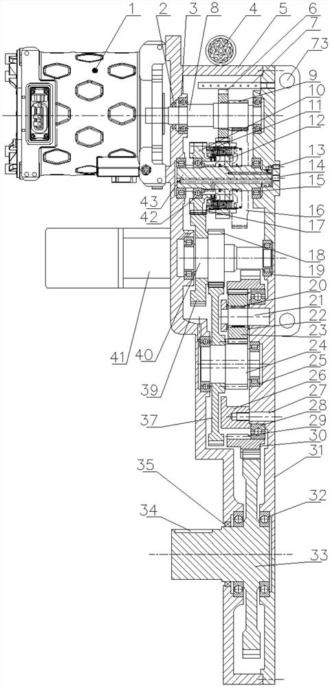
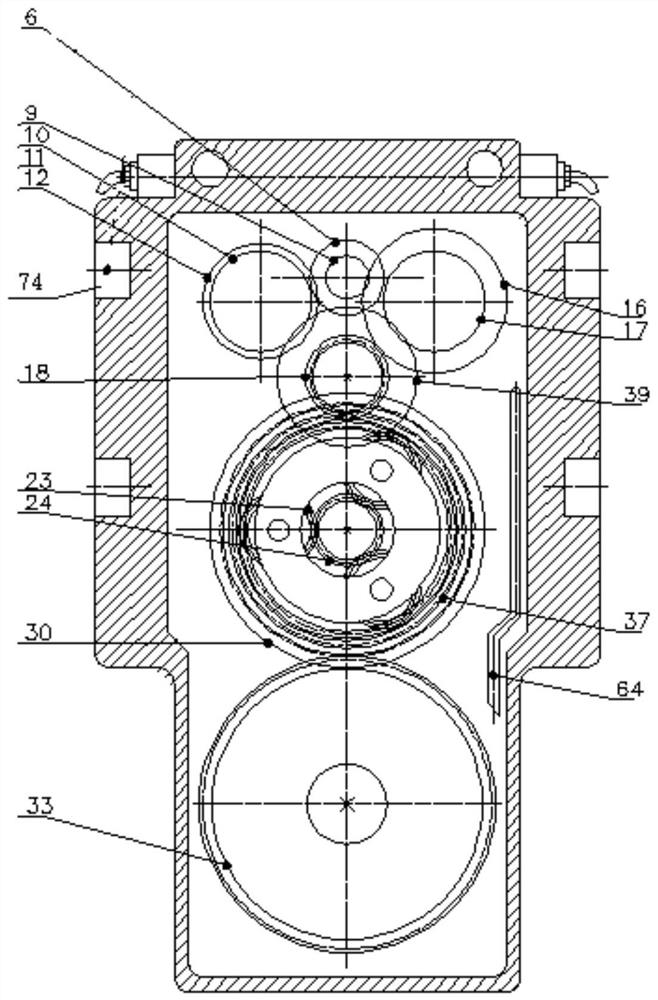
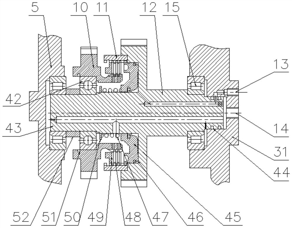
The invention relates to a hub reduction structure with a diaphragm clutch, and belongs to the field of amphibious wheeled vehicle speed reduction. The hub reduction structure comprises an input shaft, speed reduction shafts and a common shaft, wherein the speed reduction shafts are connected with the input shaft, a speed reducing wheel set is arranged between the speed reduction shafts and the input shaft, output gears are further arranged on the speed reduction shafts, the output gears are rotationally arranged on the speed reduction shafts, diaphragm clutches are arranged between speed reduction gears and the speed reduction shafts, the speed reduction gears are connected with or disconnected from the speed reduction shafts through the diaphragm clutches, a common input gear is arrangedon the common shaft, the number of the speed reduction shafts is two, and the speed reduction gears on the two speed reduction shafts mesh with the common input gear. According to the hub reduction structure with the diaphragm clutch, the high and low speed output is achieved, the requirements of wheel type amphibious vehicles for high-speed and low-speed working conditions of the hub reduction is met, a high-density motor can be used in a matching mode, high-speed input can be achieved, the weight is low and the efficiency is high, a hybrid transmission structure is compact, the structure ofa lifting system is simplified, the requirement for the lifting function is met, the structure can adapt to different pavements, space is fully utilized, and the weight is light.

Description

technical field [0001] The invention belongs to the field of deceleration equipment for amphibious wheeled vehicles, and relates to a wheel-side deceleration structure with a diaphragm clutch. Background technique [0002] In the field of amphibious wheeled vehicle equipment, if the wheel-side reducer meets the actual operating conditions of light-load high-speed and heavy-load low-speed, it can give full play to the power of the prime mover; if it solves the problem of high-speed input, it can be matched with high-density high-speed motors, In order to reduce the weight of the whole machine; at the same time, the gearbox is integrated with the structure of the lifting system, which can simplify the lifting system; according to actual use, the more compact the structure of the wheel reducer, the better, and the lighter the weight, the better. [0003] Most of the reducers of the current amphibious wheeled vehicles do not have the gear function, and cannot meet the dual worki...

Claims


Application Information

Patent Timeline
IPC IPC(8): F16H3/44F16H3/087F16H57/04F16D25/0635
CPCF16H3/44F16H57/04F16H3/087F16H57/0413F16H57/0456F16H57/0482F16D25/0635
Inventor 吴志雄彭宇曾林郭丽明
Owner CHONGQING QINGPING MACHINERY
Features
  • R&D
  • Intellectual Property
  • Life Sciences
  • Materials
  • Tech Scout
  • Unparalleled Data Quality
  • Higher Quality Content
  • 60% Fewer Hallucinations
Learn More