Moisture-proof and water-removing cable trench for communication base station

A communication base station, hydropower technology, applied in cable installation, ground cable installation, electrical components, etc., can solve the problem of easy water ingress and humidity in the cable trench, and achieve the effect of accelerating the evaporation rate

Inactive Publication Date: 2021-01-12
湖州浪佩智能科技有限公司
View PDF0 Cites 1 Cited by
  • Summary
  • Abstract
  • Description
  • Claims
  • Application Information

AI Technical Summary

Problems solved by technology

[0005] The purpose of the present invention is to provide a moisture-proof and water-removing cable trench for communication base stations with moisture-proof and waterproof functions to solve the problem that the cable trench is prone to water and moisture

Method used


Image

  • Moisture-proof and water-removing cable trench for communication base station
  • Moisture-proof and water-removing cable trench for communication base station
  • Moisture-proof and water-removing cable trench for communication base station

Examples


Embodiment 1

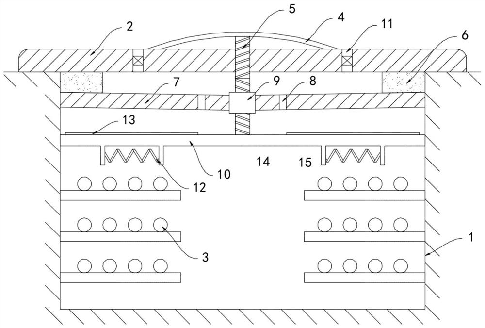
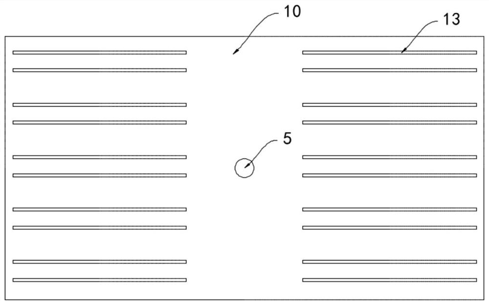
[0021] Such as Figure 1-2 As shown, a moisture-proof and water-removing cable trench for a communication base station includes a trench body 1, a cover plate 2 and a cable 3 arranged in the trench body 1, and the cover plate 2 is provided with a vent hole 11, and the vent hole A pressure valve is installed in 11, and a flexible pedal 4 is installed on the upper surface of the cover plate 2. The flexible pedal 4 is arranged in an upwardly arched arc shape. The flexible pedal 4 has good deformability and elasticity, and can automatically deform after being deformed by force. Reset, the lower surface of the flexible pedal 4 is fixedly connected with a threaded rod 5, the thread on the surface of the threaded rod 5 is a coarse thread, the thread rise angle is greater than the equivalent friction angle of the screw pair, does not have self-locking property, the lower end of the threaded rod 5 penetrates the cover The plate 2 extends to the inside of the channel body 1, the cover p...

Embodiment 2

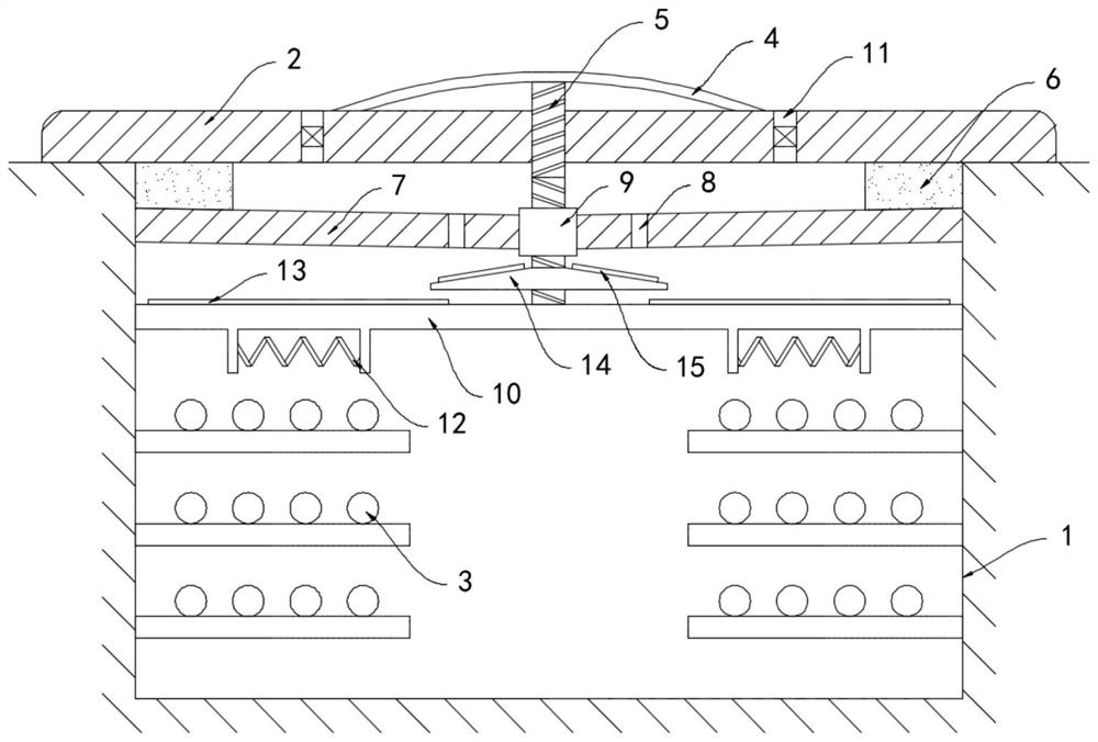
[0027] Such as image 3 As shown, the difference between this embodiment and Embodiment 1 is that a rotating disk 14 is provided below the pressing plate 7, and the rotating disk 14 is coaxially fixedly sleeved outside the threaded rod 5, and the upper surface of the rotating disk 14 is fixedly connected with multiple A plurality of shunt bars 15 arranged in an annular array all extend along the radial direction of the rotating disk 14 .

[0028] In this embodiment, the threaded rod 5 can drive the rotating disk to rotate synchronously, and the rainwater in the water-absorbing ring 6 is squeezed out and drips on the upper surface of the rotating disk 14. According to the atomization principle of the rotating disk, part of the rainwater will be atomized, and at the same time Under the action of the centrifugal force, the rainwater can be evenly thrown to the heating plate 10, further accelerating the evaporation rate of the rainwater.

[0029] In this embodiment, during the ro...


PUM


Abstract

The invention belongs to the field of communication facilities, and particularly relates to a moisture-proof and water-removing cable trench for a communication base station, which comprises a trenchbody, a cover plate and a cable arranged in the trench body. A flexible pedal is arranged on the upper surface of the cover plate and is in an upwards arched cambered surface shape. A threaded rod isfixedly connected to the lower surface of the flexible pedal, the lower end of the threaded rod penetrates through the cover plate and extends into the channel body, a thread is arranged in the coverplate and is in threaded fit with the threaded rod, a water absorption ring is fixedly connected to the lower surface of the cover plate, and a pressing plate is slidably connected to the inner side wall of the channel body; a plurality of drainage holes are formed in the pressing plate, a threaded cylinder is fixedly embedded in the pressing plate, and the lower end of the threaded rod penetratesthrough the threaded cylinder and is in threaded fit with the threaded cylinder. Rainwater entering the channel body can be rapidly electrolyzed, heated and evaporated, rainwater is effectively prevented from further permeating, the good moisture-proof and waterproof effects are achieved, and corrosion to a cable is avoided.

Description

technical field [0001] The invention belongs to the field of communication facilities, in particular to a moisture-proof and water-removing cable trench for a communication base station. Background technique [0002] The communication base station refers to the radio transceiver station that transmits information between the mobile communication switching center and the mobile phone terminal in a certain radio coverage area. Most of the communication base stations are equipped with cable trenches for the embedding of communication cables. [0003] The traditional cable trench is a trench with a cover plate, which is used to prevent rainwater and sundries from entering the trench. However, after the cover plate is used for a long time, or after multiple opening and closing operations, the edge of the cover body is aged and worn, and even warped. The tightness of the channel and the channel is reduced, causing rainwater and sundries to enter through the gap between the channel...

Claims


Application Information

Patent Timeline
Patent Type & Authority Applications(China)
IPC IPC(8): H02G9/02
CPCH02G9/025
Inventor 王云
Owner 湖州浪佩智能科技有限公司
Why Eureka
Try Eureka