Dynamic pressurizing filter pressing plate of filter press

A filter press plate and filter press technology, applied in filtration separation, separation methods, chemical instruments and methods, etc., can solve the problem of low filtration efficiency, increase the filter press cost, and increase the filter press load, etc. problems, to achieve the effect of enhancing the filter press effect, reducing the workload, and enhancing the safety of use

Active Publication Date: 2021-01-15
泉州市创绿机械工贸有限公司
View PDF13 Cites 6 Cited by
  • Summary
  • Abstract
  • Description
  • Claims
  • Application Information

AI Technical Summary

Problems solved by technology

In the process of pressing the filter, there is a problem that the filter residue blocks the filter cloth and affects the pressing of the filter. For this reason, Patent Document 1 proposes a filter press, which is provided with a spring between the filter cloth and the filter plate and can rotate The unique push rod structure, the joint action of the spring and the push rod makes the relative movement between the filter cloth and the filter plate possible, and to a certain extent avoids the situation that the filter holes on the filter cloth are blocked by fixed particles. However, due to There is a spring structure, so the structure of the push rod cannot completely cover the entire filter cloth, and because the longitudinal section area of ​​the push rod gradually decreases toward the side of the filter cloth, the end of the push rod away from the filter plate is inverted Rounded corners, therefore, the push rod is not a flexible structure, and the filter cloth may be damaged by cutting or other damage during the rotation process. The material liquid passes through the feed port and drives the fan blades to rotate. At the beginning of flushing, the fan blades rotate faster because the filter chamber is not filled with liquid, but after the liquid is filled, the liquid passing through the feed port will become less Or the flow is slow, and at this time, the fan blade may rotate slowly or cannot rotate, and the push rod at this time may not rotate. Therefore, there is a problem that the filter cloth and the filter plate cannot be relatively separated and bonded. Case
Another example is patent document 2, which discloses a high-efficiency box-type fi

Method used


Image

  • Dynamic pressurizing filter pressing plate of filter press
  • Dynamic pressurizing filter pressing plate of filter press
  • Dynamic pressurizing filter pressing plate of filter press

Examples


Embodiment Construction

[0042] The present invention will be further described below in conjunction with the examples, but the present invention is not limited in any way, and any transformation or substitution made based on the teaching of the present invention belongs to the protection scope of the present invention.

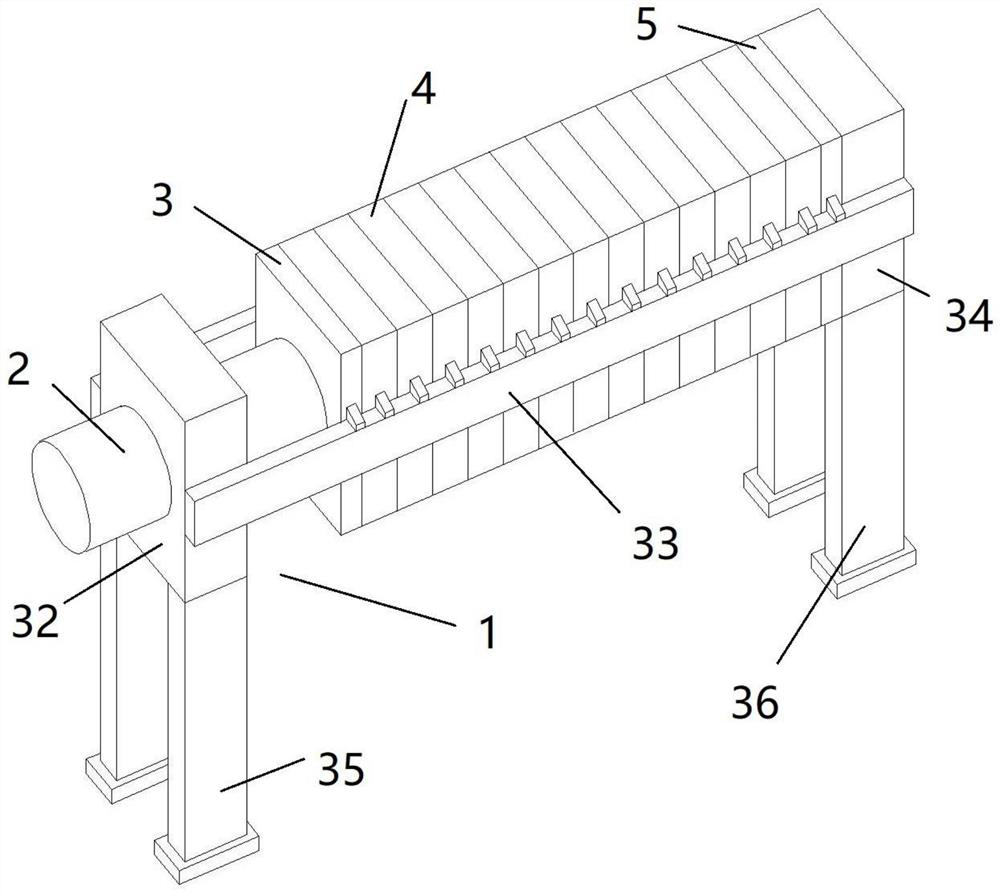
[0043] like figure 1 As shown, the filter press of the present invention includes: a frame 1, a hydraulic cylinder 2, a pressing plate 3, a filter plate 4 and a thrust plate 5, and the frame 1 includes a left support frame 32, a crossbeam 33 and a right support frame 34 , the two ends of the beam 33 are respectively connected to the left support frame 32 and the right support frame 34, the compression plate 3 and the filter plate 4 are slidably arranged on the beam 33, the hydraulic cylinder 2 is fixedly arranged on the left support frame 32, and the end is connected with the compression The plates 3 are fixedly connected, and the thrust plate 5 is fixedly arranged on the right suppo...


PUM


Abstract

The invention discloses a dynamic pressurizing filter pressing plate of a filter press, which is characterized in that flexible linkage mechanisms are arranged on the surfaces of the two sides of a filter plate, flowing liquid is arranged in the flexible linkage mechanisms, the flexible linkage mechanisms are arranged to be of a structure similar to a spider web, and thus the up-and-down fluctuation action of filter cloth can be controlled on the whole. Meanwhile, a rotary driving mechanism is arranged in a feed liquid cylinder mounted in a central through hole of the filter pressing plate androtates by taking passing feed liquid as a driving force, and the rotary motion is converted into power for intermittently extruding the flexible linkage mechanisms, so that the filter pressing effect and efficiency of the equipment are further improved. Meanwhile, the conical inner wall structure designed in the feed liquid cylinder can further improve the power output efficiency, and the filterpressing effect is further improved.

Description

technical field [0001] The invention relates to the technical field of solid-liquid separation, in particular to a dynamic pressure filter plate of a filter press. Background technique [0002] Filter press, especially box-type filter press, is a commonly used solid-liquid separation equipment, which has the advantages of high filtration pressure, large single-machine filtration area, low liquid content of filter cake, light weight of filter plate, and low maintenance and operation costs. Therefore, its application is more extensive. The box-type filter press consists of a set of filter chambers arranged alternately with filter plates and filter frames. The filter frames and filter plates are provided with through holes. After assembly, a complete channel can be formed, and the suspension, washing water and filtrate can be introduced. Under the pressure of the feeding pump, the material liquid to be filtered is sent into each filter chamber, and the solid and liquid are sep...

Claims


Application Information

Patent Timeline
IPC IPC(8): B01D25/12
CPCB01D25/12
Inventor 王金伟庞碧达
Owner 泉州市创绿机械工贸有限公司
Why Eureka
Try Eureka