
U-shaped bolt bottom plate drilling device

A drilling device and bolt technology, applied in positioning devices, clamping devices, boring/drilling, etc., can solve the problems of staff injury, cleaning difficulties, low efficiency, etc., and achieve the effect of improving work efficiency

Inactive Publication Date: 2021-01-15
HUBEI HAILIAN TECH CONSULTATION CO LTD
View PDF0 Cites 5 Cited by
  • Summary
  • Abstract
  • Description
  • Claims
  • Application Information

AI Technical Summary

Problems solved by technology

[0002] The existing U-bolt bottom plate drilling process is performed by hand-held drilling machines, which is inefficient, and when drilling, it is easy to generate more splashes of iron filings, which is not only difficult to clean, but also easily causes injuries to the staff.

Method used


Image

  • U-shaped bolt bottom plate drilling device
  • U-shaped bolt bottom plate drilling device
  • U-shaped bolt bottom plate drilling device

Examples


Embodiment 1

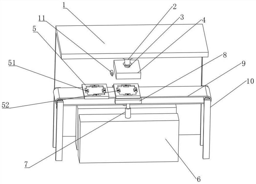
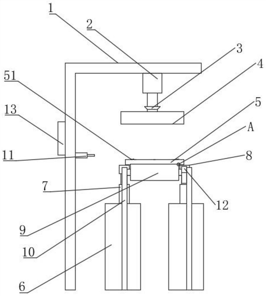
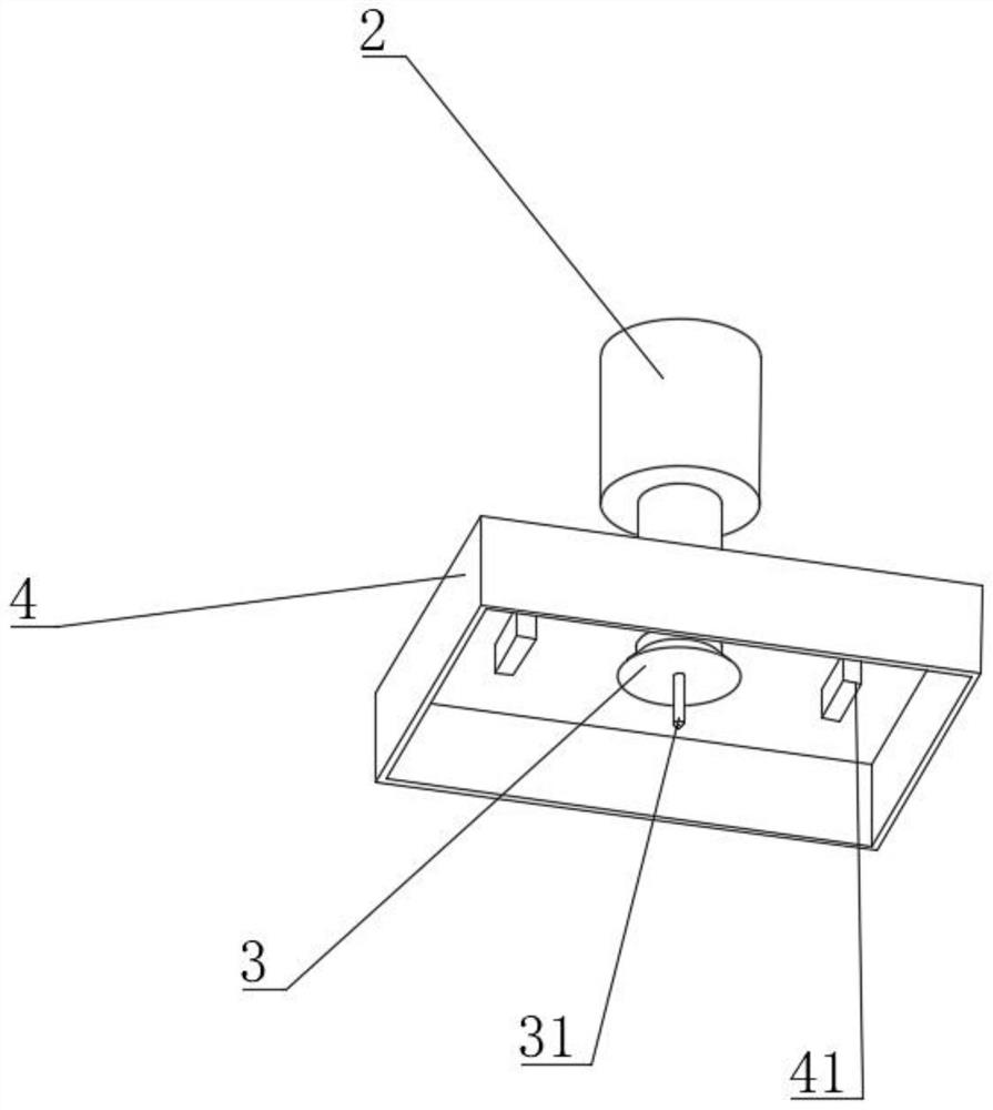
[0022] combine Figure 1-6 , a U-bolt floor drilling device, comprising a support body 1, a support column 10 is provided below the support body 1, a second motor 12 is fixed on the support column 10, and the output of the second motor 12 A rotating shaft is installed at the end, and the rotating shaft is fixed with a conveyor belt 9. The supporting column 10 is set to support and fix the second motor 12. The second motor 12 is set to drive the rotating shaft. The rotating shaft is set to drive the conveyor belt 9. The conveyor belt 9 is set to realize Continuous production, the upper part of the support body 1 is fixed with a first electric telescopic rod 2, the movable end of the first electric telescopic rod 2 is fixed with a first motor 3, and the output end of the first motor 3 is equipped with a drill bit 31 , the first telescopic rod 2 is set to adjust the up and down position of the drill bit, so as to facilitate drilling of the U-shaped bolt base plate, the outer shel...

Embodiment 2

[0028] A U-bolt bottom plate drilling device, this embodiment further defines the device on the basis of the embodiment.

[0029] The support block 8 is provided with a groove, and a second spring 81 is installed in the groove, and a second resisting block 82 is fixed on the second spring 81, and the second spring 81 and the second resisting block 82 The cooperation realizes that the vibration energy of the carrier 5 is effectively absorbed by the second spring 81 on the support block 8 during drilling, thereby improving the stability of drilling.


PUM


Abstract

The invention discloses a U-shaped bolt bottom plate drilling device, the device comprises a supporting body, supporting columns are arranged below the supporting body, a second motor is fixed to thesupporting columns, a rotating shaft is installed at the output end of the second motor, a conveying belt is rotationally fixed to the rotating shaft, a first electric telescopic rod is fixed to the upper portion of the supporting body, a first motor is fixed to the movable end of the first electric telescopic rod, a drill bit is installed at the output end of the first motor, an outer cover shellis fixed to an outer shell of the first motor, electromagnetic magnets are installed on the outer cover shell, a carrier is installed on the conveying belt, an infrared locator and a controller are arranged in the middle of the supporting body, placing tables are symmetrically arranged on the two sides of the conveying belt, second electric telescopic rods are installed on the placing tables correspondingly, and supporting blocks are installed at the movable ends of the second electric telescopic rods correspondingly. The U-shaped bolt bottom plate drilling device can achieve continuous drilling of a U-shaped bolt bottom plate and collection of scraps.

Description

technical field [0001] The invention relates to the field of mechanical processing, in particular to a U-bolt bottom plate drilling device. Background technique [0002] The existing U-bolt bottom plate drilling process is performed by hand-held drilling machines, which is inefficient, and when drilling, it is easy to generate more splashes of iron filings, which is not only difficult to clean, but also easily causes injuries to the staff. . Contents of the invention [0003] The object of the present invention is to provide a U-bolt bottom plate drilling device to solve the problems raised in the above-mentioned background technology. [0004] To achieve the above object, the present invention provides the following technical solutions: [0005] A U-shaped bolt bottom plate drilling device, comprising a support body, a support column is arranged below the support body, a second motor is fixed on the support column, and a rotating shaft is installed at the output end of ...

Claims


Application Information

Patent Timeline
Patent Type & Authority Applications(China)
IPC IPC(8): B23B41/00B23Q3/00B23Q11/08B23Q7/00B23Q11/00
CPCB23B41/00B23Q3/00B23Q7/003B23Q11/0064B23Q11/08B23Q2703/10
Inventor 石小龙张亚蒙赵秀碧
Owner HUBEI HAILIAN TECH CONSULTATION CO LTD
Learn More