Cosmetic filling device for intelligent production

A filling device and intelligent production technology, which is applied in the field of cosmetics filling devices for intelligent production, can solve the problems of inconvenient adjustment and inapplicability of cosmetic filling volume, and achieve the effect of strong practicability and reduced defective rate

Inactive Publication Date: 2021-01-15
温州旭珊贸易有限公司
0 Cites 1 Cited by

AI-Extracted Technical Summary

Problems solved by technology

[0006] Aiming at the deficiencies of the prior art, the present invention provides an intelligently produced cosmetic filling device, capable of intelligently detecting the packaging bottle before filling, clamping and fixing the packaging bottle during filling, and being able to monitor the amount o...

Method used

The interior of clamping plate 25 is movably connected with photosensitive assembly 2 26, and the interior of filling assembly 21 is fixedly connected with light strip 27, and mobile assembly 24 is mainly made up of connecting rod, moving plate, slide block, chute, and rotating shaft The outside of 23 is fixedly connected with a connecting rod, and the outside of the connecting rod is movably connected with a slide block, and the outside of the connecting rod is movably connected with a moving plate, and the surface of the moving plate is provided with a chute, and the slide block and the chute are slidably connected. The interior is fixedly connected with four contact rods. The position and specifications of the four contact rods are all matched with the moving plate, which can drive the clamping plate 25 to move and adjust the opening and closing size of the cosmetic feeding port. The moving position of the moving plate is limited. When the moving plate moves to contact with the contact rod four, the rotating shaft 23 will no longer rotate forward. The moving plate continues to move to the right, causing the opening to become larger. Photosensitive component 2 26 is mainly composed of light-shielding shell 2, photoresistor 2, and light-transmitting hole 2. The interior of clamping plate 25 is fixedly connected with light-shielding shell 2. The interior of shell 2 is fixedly connected with photoresistor 2, the surface of light-shielding shell 2 is provided with light-transmitting hole 2, and the inside of light strip 27 is provided with lamp beads. , rotating shaft 23, rotating rod 12, electromagnet one 14, electromagnet two, contact rod one 10, contact rod two 20, contact rod three, contact rod four, conveyor belt, light strip 27, photoresistor one, photoresistor two, The driving power supply is electrically connected to the control center, which makes the internal components of the cosmetics filling device interrelated, greatly improvin...

Abstract

The invention relates to the technical field of cosmetic production equipment, and discloses an cosmetic filling device for intelligent production. The cosmetic filling device for intelligent production comprises a workbench, wherein a shell is fixedly connected to the exterior of the workbench; and a rotating shaft is movably connected to the interior of the shell. Through the interaction of a rotating shaft, a gear I, a rack, a moving frame, a connecting assembly, a clamping plate, a contact rod I, a spring I and a limiting assembly, the state of a packaging bottle can be intelligently detected, and the packaging bottle can be clamped and fixed in the filling process, so that the situation that cosmetics are sprinkled on a conveying belt due to the fact that the device continues to conduct filling when packaging bottles incline at the filling position or fall down due to inertia can be avoided, meanwhile, the packaging bottles can be kept in a stable state in the filling process, andthen the defective rate of cosmetic production can be reduced; and in addition, production and manufacturing of the cosmetics can be changed from conventional manufacturing to intelligent manufacturing, so that the requirements of actual production are better met.

Application Domain

Safety device in filling machinery

Technology Topic

WorkbenchIndustrial engineering +2

Image

  • Cosmetic filling device for intelligent production
  • Cosmetic filling device for intelligent production
  • Cosmetic filling device for intelligent production

Examples

  • Experimental program(1)

Example Embodiment

[0027] The technical solutions in the embodiments of the present invention will be clearly and completely described below with reference to the accompanying drawings in the embodiments of the present invention. Obviously, the described embodiments are only a part of the embodiments of the present invention, but not all of the embodiments. Based on the embodiments of the present invention, all other embodiments obtained by those of ordinary skill in the art without creative efforts shall fall within the protection scope of the present invention.
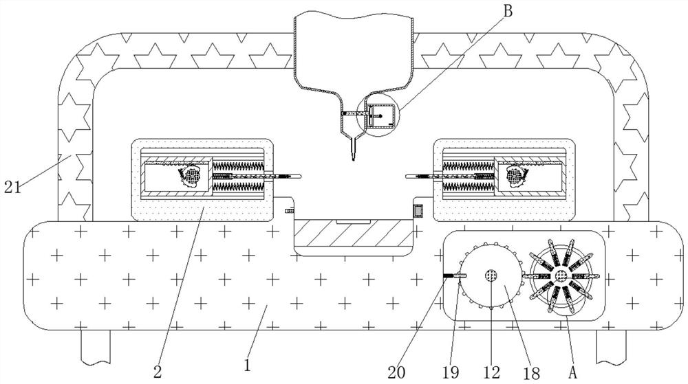
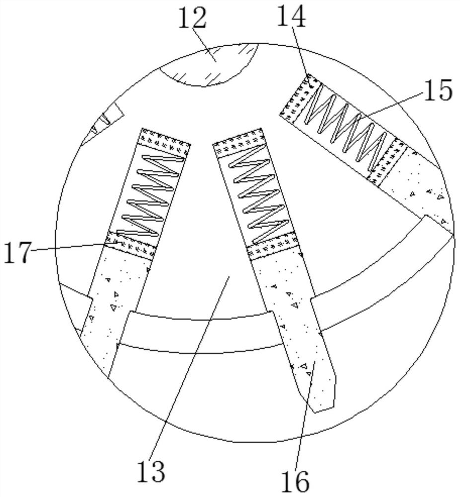
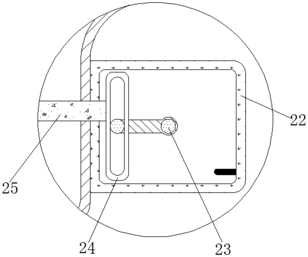
[0028] see Figure 1-7 , an intelligent production cosmetic filling device, comprising a workbench 1, a photosensitive component 1 is fixedly connected to the interior of the workbench 1, and the photosensitive component 1 is mainly composed of a photoresistor, a light-shielding shell, and a light-transmitting hole. A light-shielding shell 1 is fixedly connected inside, a photoresistor is fixedly connected inside the light-shielding shell 1, a light-transmitting hole 1 is opened on the surface of the light-shielding shell 1, and a spotlight is fixedly connected inside the workbench 1, and the position and specification of the spotlight are the same as Once the photosensitive components are matched, the control device can perform the next operation after the bottle reaches the filling position, thereby greatly improving the intelligence of the filling device.
[0029]The outer part of the workbench 1 is fixedly connected with the outer shell 2; the inner part of the outer shell 2 is movably connected with a rotating shaft 3; There is a moving frame 6, the inner surface of the moving frame 6 is fixedly connected with a rack 7, the outside of the moving frame 6 is movably connected with a connecting assembly 8, the interior of the connecting assembly 8 is movably connected with a spring-9, and the outside of the connecting assembly 8 is movably connected with a Touch rod 1 10, a splint 11 is fixedly connected to the outside of the connecting component 8, and the limit component 5 is mainly composed of a ratchet, a clamping rod, a spring 3, an electromagnet 2, and a short column. A short post is fixedly connected to the inside of the platform 1, and a clamping rod is connected to the outer movable sleeve of the short post. , the electromagnet 2 is fixedly connected with the worktable 1, the clamping rod is movably connected with the ratchet, the outside of the moving frame 6 is fixedly connected with a spring 4, and the spring 4 is fixedly connected with the worktable 1. After the cosmetic filling is completed, the splint 11 is driven to reset, thereby saving energy consumption.
[0030] A rotating rod 12 is movably connected to the inside of the workbench 1, a runner 13 is fixedly sleeved on the outside of the rotating rod 12, an electromagnet 14 is fixedly connected to the inside of the runner 13, and a spring 2 15 is movably connected to the interior of the runner 13. The inside of the runner 13 is movably sleeved with a push rod 16, the outside of the push rod 16 is fixedly connected with an iron block 17, the inside of the worktable 1 is movably connected with a second gear 18, and the outside of the second gear 18 is fixedly connected with a stop rod 19. The interior of 2 is fixedly connected with a limit plate, the surface of the limit plate is provided with a limit slot, the moving frame 6 is slidably connected with the limit slot, the position and size of the stop rod 19 match the second contact rod 20, and the electromagnet one 14. The position and specifications of the iron block 17 are matched with the iron block 17, and a conveyor belt is movably connected to the outside of the workbench 1.
[0031] A contact rod 20 is fixedly connected to the inside of the worktable 1, a filling assembly 21 is movably connected to the outside of the worktable 1, a box body 22 is movably connected to the outside of the filling assembly 21, and a rotating shaft 23 is movably connected to the inside of the box body 22. , the outside of the rotating shaft 23 is movably connected with a moving assembly 24, the outside of the moving assembly 24 is fixedly connected with a clamping plate 25, the connecting assembly 8 is mainly composed of a sleeve, a long rod, a contact rod three, and a spring five, and the outside of the moving frame 6 is fixed A sleeve is connected, the inner movable connection of the sleeve is with a spring five, the inner movable sleeve of the sleeve is connected with a long rod, the external fixed connection of the long rod is a contact rod three, the long rod is fixedly connected with the splint 11, the contact rod one 10 is connected with The long rod is movably connected, which can hold the packaging bottle stably. The filling assembly 21 is mainly composed of a bracket, a storage cylinder, a discharge pipe, and an injection pipe. The material storage cylinder, the outer part of the material storage cylinder is fixedly connected with the discharge pipe, the outside of the discharge pipe is fixedly connected with the injection pipe, the light strip 27 is fixed inside the discharge pipe, the box body 22 is fixedly connected to the outside of the discharge pipe, The card board 25 is movably plugged with the discharge pipe.
[0032] The interior of the card board 25 is movably connected with a photosensitive assembly 26, the interior of the filling assembly 21 is fixedly connected with a light strip 27, and the moving assembly 24 is mainly composed of a connecting rod, a moving plate, a slider, and a chute. A connecting rod is fixedly connected, a slider is movably connected to the outside of the connecting rod, a moving plate is movably connected to the outside of the connecting rod, and a sliding groove is formed on the surface of the moving plate. There are four contact rods. The position and specifications of the four contact rods are matched with the moving plate, which can drive the clamping plate 25 to move to adjust the opening and closing size of the cosmetic discharge port. In addition, the fourth contact rod can adjust the moving position of the moving plate. Limit, when the moving plate moves to contact with the contact rod 4, the rotating shaft 23 will no longer rotate forward, and when the position needs to be adjusted again, it will be reversed, which can prevent the moving plate from continuing when the feeding port needs to be adjusted down. Moving to the right causes the feeding opening to become larger. The second photosensitive component 26 is mainly composed of the second light-shielding shell, the second photoresistor, and the second light-transmitting hole. The interior of the card board 25 is fixedly connected with the second light-shielding shell. The second photoresistor is fixedly connected inside, the second light-transmitting hole is opened on the surface of the shading shell 2, and the lamp strip 27 is provided with a lamp bead inside. 23. Rod 12, Electromagnet One 14, Electromagnet Two, Contact Rod One 10, Contact Rod Two 20, Contact Rod Three, Contact Rod Four, Conveyor Belt, Light Strip 27, Photoresistor One, Photoresistor Two, Drive Power All It is electrically connected to the control center, so that the components inside the cosmetic filling device are interconnected, which greatly improves the intelligence of the filling device, which is conducive to the transformation of cosmetic production and filling from conventional production to intelligent manufacturing, which is more in line with actual production. need.
[0033] Working principle: Before the device is used, the corresponding lamp beads are controlled by the control center to light up according to the capacity of the packaging screen. At the same time, the corresponding number of electromagnets-14 are energized through the control center. In addition, the control center also controls the drive power to drive. The rotation of the rotation shaft 23, the rotation of the rotation shaft 23 drives the rotation of the connecting rod. Under the interaction of the chute and the slider, the rotation of the connecting rod can drive the moving plate to move, and the movement of the moving plate drives the clamping plate 25 to move. When the second photoresistor receives the light emitted by the lamp bead, the light intensity it receives increases, the resistance value becomes smaller, and the passing current becomes larger. At this time, the control center controls the driving power to stop driving the rotating shaft 23 to rotate; 14 is energized to generate magnetism and the iron block 17 attracts each other, thereby driving the iron block 17 to move in the direction of the electromagnet one 14, and the iron block 17 moves to drive the push rod 16 to move, so that part of the push rod 16 moves to the inside of the runner 13, and then Realize the adjustment of the amount of cosmetic filling.
[0034] During the use of the device, the control center controls the operation of the conveyor belt to drive the packaging bottle to move. When the packaging bottle moves to block the light emitted by the spotlight, the photoresistor cannot receive the light emitted by the spotlight. The light intensity of the photoresistor decreases, the resistance value of the photoresistor 1 increases, and the passing current becomes smaller. At this time, the control center controls the driving power to drive the rotation of the rotating shaft 3. At the same time, the control center also controls the conveyor belt to stop running. The rotation of the rotating shaft 3 drives the gear 1 to rotate. , the rotation of gear one 4 drives the rack 7 to move, the rack 7 moves to drive the moving frame 6 to move, the moving frame 6 moves to drive the sleeve to move, the sleeve moves to move the long rod, the long rod moves to drive the splint 11 to move, and the moving frame 6 moves The movement will squeeze the spring 4. When the splint 11 does not touch the packaging bottle when it moves to the limit value, the packaging bottle may fall over at this time. The control center controls the driving power to stop driving the shaft 3 to rotate. The control electromagnet II is energized, and the electromagnet II after electrification generates magnetism to attract the clamping rod, so that one end of the clamping rod is separated from the ratchet wheel. At this time, under the action of the four elastic forces of the spring, the moving frame 6 will move in the opposite direction and drive the The splint 11 is reset, and the control center also controls the conveyor belt to continue to work; when the splint 11 moves to the contact rod and the packaging bottle, the moving frame 6 continues to move, under the action of the spring one 9, the contact rod one 10 moves to the long The inside of the rod enables the splint 11 to be in full contact with the packaging bottle. When the moving frame 6 moves until the contact rod 3 is in contact with the sleeve, the control center controls the driving power supply to stop the rotation of the driving shaft 3. At this time, the device starts to carry out the filling of cosmetics, The control center controls the rotation of the rotating rod 12 .
[0035] The rotation of the rotation rod 12 drives the rotation of the runner 13, the rotation of the rotation wheel 13 drives the rotation of the push rod 16, the rotation of the push rod 16 drives the rotation of the second gear 18, and the rotation of the second gear 18 drives the rotation of the blocking rod 19. When the 20 contacts, the control center controls the drive power to stop driving the rotating rod 12 to rotate, and at the same time, the control center controls the second electromagnet to be energized. At the same time, under the action of the four elastic forces of the spring, the moving frame 6 will move in the reverse direction and drive the splint 11 to reset. In addition, the control center also controls the operation of the conveyor belt. The unfilled packaging bottle is transported to the filling position. When the next packaging bottle reaches the designated position, the control center will control the power off of the second electromagnet. After the power failure, the second electromagnet loses its magnetism. The reset of the lever continues with the ratchet basis, in addition, the control center also controls other components to operate and continue to the next filling.
[0036] Although embodiments of the present invention have been shown and described, it will be understood by those skilled in the art that various changes, modifications, and substitutions can be made in these embodiments without departing from the principle and spirit of the invention and modifications, the scope of the invention is defined by the appended claims and their equivalents.

PUM

no PUM

Description & Claims & Application Information

We can also present the details of the Description, Claims and Application information to help users get a comprehensive understanding of the technical details of the patent, such as background art, summary of invention, brief description of drawings, description of embodiments, and other original content. On the other hand, users can also determine the specific scope of protection of the technology through the list of claims; as well as understand the changes in the life cycle of the technology with the presentation of the patent timeline. Login to view more.

Similar technology patents

Polishing solution for optics lens

InactiveCN106366939AGood polishing performanceReduce defective rate
Owner:DONGXING HUAHONG OPTICAL TECH

Split type stator structure

Owner:东莞福登机电有限公司

Classification and recommendation of technical efficacy words

  • Reduce defective rate
  • Practical

User behavior self-learning air conditioning system and control method thereof

ActiveCN105318499AConvenience and good experiencePractical
Owner:GD MIDEA AIR-CONDITIONING EQUIP CO LTD +1

Intelligent grid comprehensive evaluating system based on analytic hierarchy process and fuzzy comprehensive evaluation

InactiveCN102663508ADemonstrate economic and social benefitsPractical
Owner:NORTHEAST POWER SCI RES INSTITUTION +2

Management system based on shared bicycle and method thereof

PendingCN107016594AReduce maintenance and management costsPractical
Owner:广东小强信息科技有限公司
Why Eureka
Try Eureka