Novel disinfection device for textiles

A disinfection device and textile technology, which is applied in the field of textiles, can solve the problems of dust raising, textile offset, dust falling again, etc., and achieve the effect of improving the cleaning effect and moving stably

Inactive Publication Date: 2021-01-15
韩兰珍
View PDF10 Cites 0 Cited by
  • Summary
  • Abstract
  • Description
  • Claims
  • Application Information

AI Technical Summary

Problems solved by technology

[0004] Although this device solves the existing problems of traditional sterilization, it still has the following disadvantages: the rotation of the cleaning disc will cause the textiles to be subjected to a force perpendicular to its moving direction. It has a certain cleaning effect, but it is easy to make the textiles shift during the moving process. At the same time, the rotating brush can be used to clean to a certain extent, but the cleaning operation is easy to cause the dust to be cleaned. Part of the problem of dust re-falling onto textiles

Method used


Image

  • Novel disinfection device for textiles
  • Novel disinfection device for textiles
  • Novel disinfection device for textiles

Examples


Embodiment 1

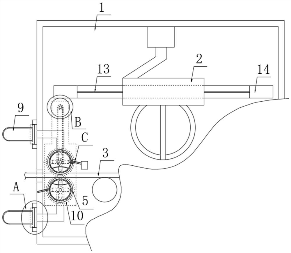
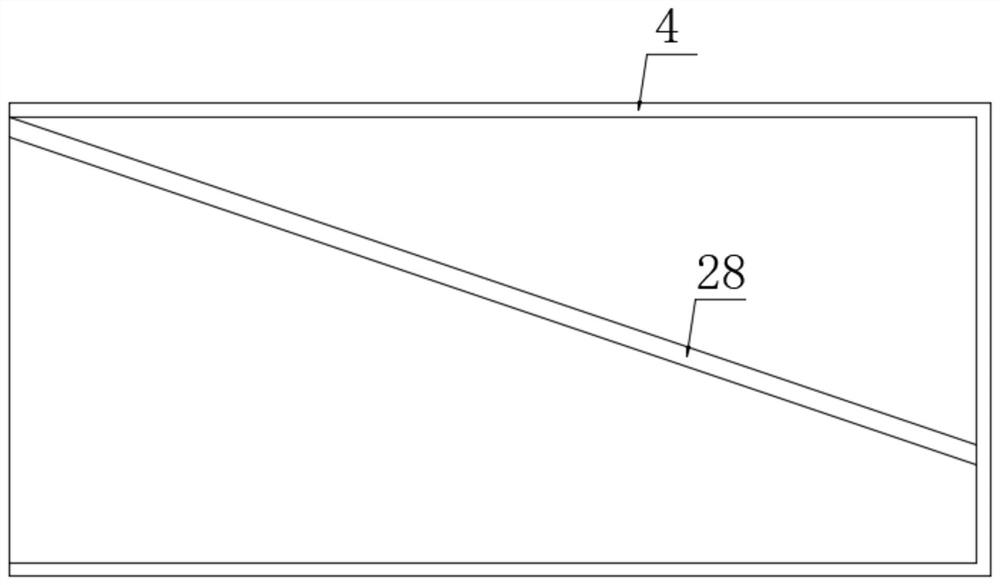
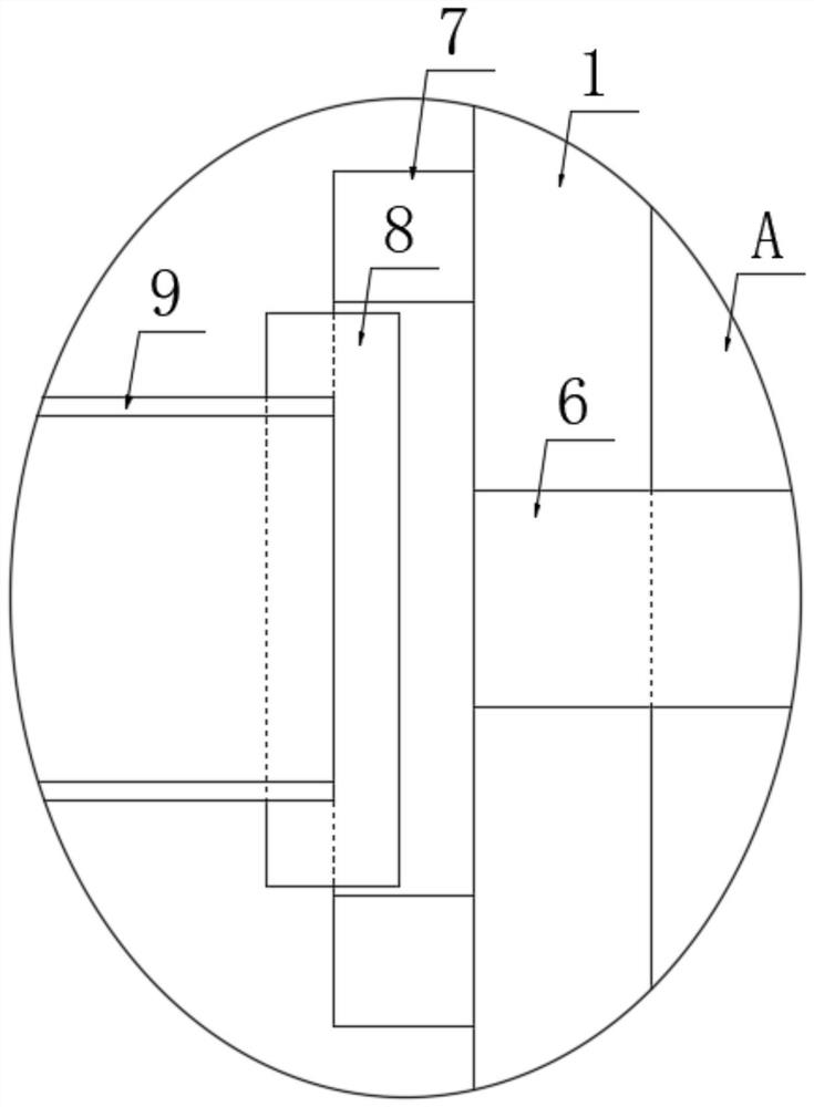
[0033] refer to Figure 1-5 , a new type of disinfection device for textiles, comprising a box body 1, a swivel 2, and a textile 3. The front inner wall of the box body 1 is installed with two dust removal rollers 4 by rotating two shafts, and the dust removal rollers 4 are located on the side of the textile 3. On both sides, the rear inner wall of the box body 1 is fixedly installed with two sealing discs 5 through a plurality of rods, and a fan blade 1 is fixedly installed on the two shafts 1, and the fan blade 1 is located in the corresponding dust removal roller 4;

[0034] There are two points worth noting above:

[0035] 1. The ends of the textiles 3 and the dust removal roller 4 away from the front side of the box body 1 are all rotatably mounted on the sealing disc 5 .

[0036] 2. The fan blade 1 can rotate with the rotation of the swivel ring 2, and the rotation of the fan blade can cause the flow of air flow, so that the dust removal roller 4 can generate the requir...

Embodiment 2

[0057] refer to Figure 6-8 The difference between this embodiment and the first embodiment is that the cleaning structure is composed of a cloth bag three, an installation cover 23, a dust collection cover 24, a rotating shaft two 25 and a fan blade two 27, and the inside of the box body 1 is fixed by three or four rods Two installation covers 23 are installed, and the side of the two installation covers 23 close to the dust removal roller 4 is fixedly connected with a dust suction cover 24, and the dust suction cover 24 is a hollow structure connected at both ends, and the installation cover 23 is far away from the dust removal roller 4 One side of each is fixedly connected with cloth bag three (not shown in the figure), and a rotating shaft two 25 is installed in two installation covers 23, and a fan blade two 27 is fixedly installed on the two rotating shafts two 25, two A linkage assembly is installed between the shaft two 25 and the shaft two; the linkage assembly is com...


PUM


Abstract

The invention discloses a novel disinfection device for textiles. The novel disinfection device comprises a box body, a rotating ring and the textiles, two dust removal rollers are rotationally installed on the inner wall of the front side of the box body through two first shafts and located at the two sides of the textiles, and two sealing discs are fixedly installed on the inner wall of the rearside of the box body through a plurality of first rods; the ends, away from the front side of the box body, of the textiles and the dust removal rollers are both rotationally installed on the sealingdiscs, the two first shafts are each fixedly provided with a first fan blade, and the first fan blades are located in the corresponding dust removal rollers; and the two sealing discs are each fixedly communicated with a connecting pipe. The novel disinfection device has the advantages that suction force generated by rotation of the first fan blades is used in cooperation with a rotating brush, dust or broken ropes adhering to the surfaces of the textiles can be better sucked away, meanwhile, normal movement of the textiles cannot be affected by rotation of the dust removal rollers, and the front surfaces and the back surfaces of the textiles are subjected to suction force interaction at the same time, so that the textiles can be moved more stably.

Description

technical field [0001] The invention relates to the technical field of textiles, in particular to a novel disinfection device for textiles. Background technique [0002] The disinfection and sterilization operation of textiles is completed by the irradiation of ultraviolet rays, but the existing disinfection and sterilization operation has some dead angles in the sterilization process, resulting in the problem of incomplete sterilization and disinfection. The sterilization operation is slow and inefficient. [0003] The authorized invention patent with the patent number CN107952089B discloses a textile disinfection device, which includes a disinfection chamber. The side wall of the disinfection chamber is provided with a feed port and a discharge port. The disinfection chamber is equipped with a motor, a rotating disc, an ultraviolet lamp, and a transmission roller. A group and two cleaning discs symmetrically arranged on both sides of the ultraviolet lamp; the motor is fix...

Claims


Application Information

Patent Timeline
Patent Type & Authority Applications(China)
IPC IPC(8): D06G1/00
CPCD06G1/00
Inventor 韩兰珍
Owner 韩兰珍
Why Eureka
Try Eureka