Supercharge Your Innovation With Domain-Expert AI Agents!

A construction gap grouting device

A gap and construction technology, applied in the field of construction gap grouting device, can solve the problems of poor grouting applicability, cumbersome operation, large quantity, etc., and achieve the effects of ensuring stability, improving applicability, and enhancing practicability

Inactive Publication Date: 2022-03-04
CHINA CONSTR EIGHT ENG DIV CORP LTD
View PDF5 Cites 0 Cited by
  • Summary
  • Abstract
  • Description
  • Claims
  • Application Information

AI Technical Summary

Problems solved by technology

[0003] The commonly used grouting machine is mainly used in grouting projects with large working surface and high grouting volume. This kind of grouting machine has defects such as large volume, complex structure, cumbersome operation and difficult maintenance. It is an important part of cement pouring in construction operations. Equipment, cement grouting devices are used more frequently, and their performance directly affects the quality of buildings. The cement grouting devices in the prior art are generally large. Although they have strong handling capacity and fast operating speed, they are less suitable for grouting some building gaps. Poor, the length of these gaps is often short but the number is large, therefore, in view of the above status quo, there is an urgent need to develop a construction gap grouting device to overcome the shortcomings in the current practical application

Method used


Image

  • A construction gap grouting device
  • A construction gap grouting device
  • A construction gap grouting device

Examples


Embodiment 1

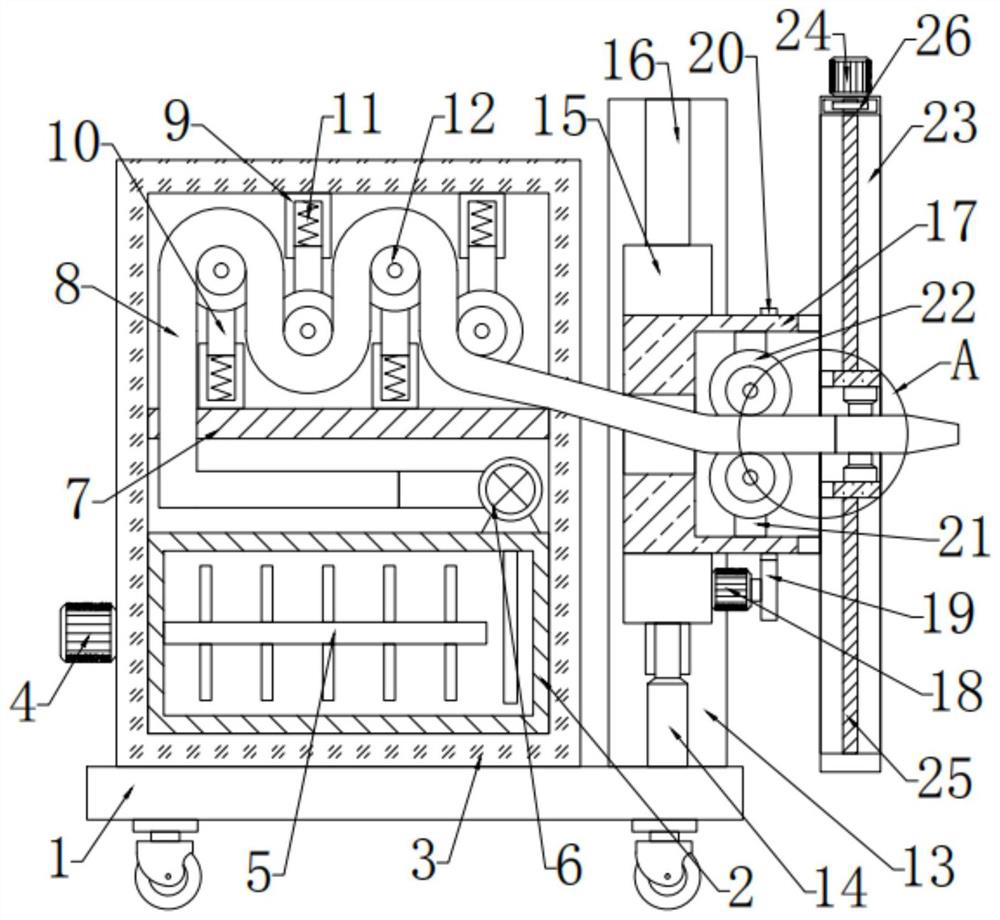
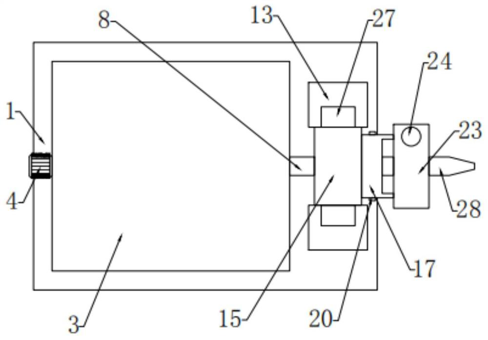
[0025] see Figure 1-4 , in an embodiment of the present invention, a construction gap grouting device includes a base plate 1, a housing 3 is fixedly connected to the top of the base plate 1, and a fixing plate 7 is fixedly connected to the inside of the housing 3, and the fixing plate 7 The lower side is provided with a material storage mechanism, and the output end of the storage mechanism is connected to the grouting head 28 arranged on the right side of the housing 3 through the material guide mechanism on the upper side of the fixed plate 7. The outer side of the grouting head 28 is provided with a 1 A fixedly connected support mechanism.

Embodiment 2

[0027] In this embodiment, the material storage mechanism includes a material storage box 2 that is bolted to the inside of the casing 3, and the left side of the storage box 2 is provided with a first motor 4 that is bolted to the casing 3. The output end of a motor 4 is connected to the stirring rod 5 arranged inside the storage box 2, and the top bolt on the right end of the storage box 2 is connected with a grouting pump 6, and the input end of the grouting pump 6 is connected to the storage box 2. The output end of the grouting pump 6 is connected to the material guide mechanism. By setting the material storage mechanism, the first motor 4 is used to drive the stirring rod 5 to rotate to stir the raw materials, so that the slurry and water are evenly mixed to ensure the effectiveness of grouting.

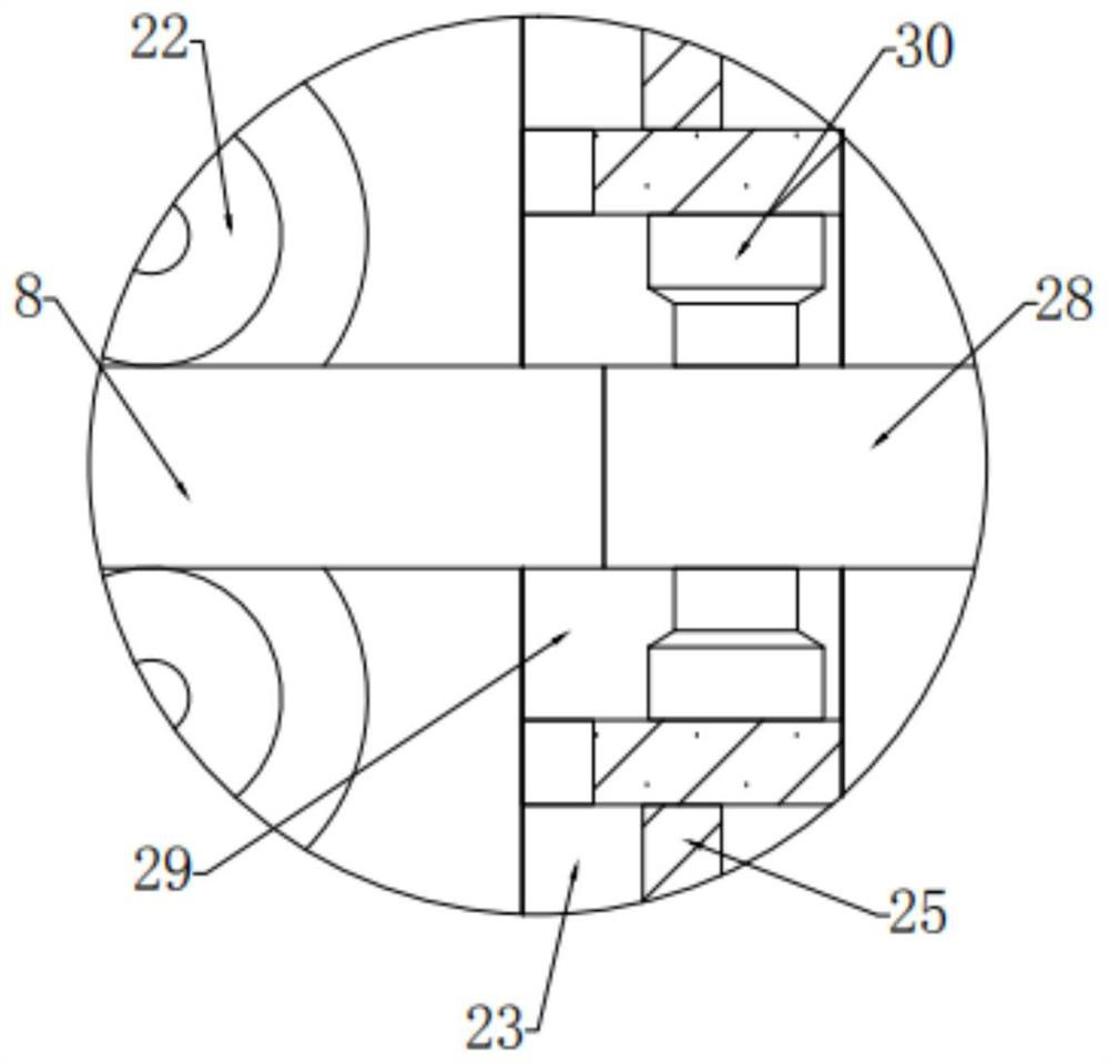
[0028] In this embodiment, the material guide mechanism includes a material guide tube 8, the input end of the material guide tube 8 is connected to the grouting pump 6, and the...


PUM


Abstract

The invention relates to the field of construction, in particular to a construction gap grouting device, comprising a base plate, a housing is fixedly connected to the top of the base plate, a fixing plate is fixedly connected to the inside of the housing, and a storage mechanism is provided on the lower side of the fixing plate. The output end is connected to the grouting head arranged on the right side of the casing by setting the material guide mechanism on the upper side of the fixed plate, and the outside of the grouting head is provided with a support mechanism fixedly connected to the bottom plate. Under the action of the spring, no matter how the grouting head moves, it will reset, so that the guide tube can always be kept in an orderly arrangement in the shell, avoiding the entanglement of the guide tube when moving, and ensuring the stability of the grouting. The three motors drive the placement frame to move in the connection frame, so that the device can grout the linear gaps on the wall, remove the grouting head, and manually control the grouting head to complete the grouting of the curved gaps.

Description

technical field [0001] The invention relates to the construction field, in particular to a construction gap grouting device. Background technique [0002] Grouting refers to the process of sending grout hydraulic pressure to the cracks of the foundation of hydraulic structures, fault fracture zones or the joints and cracks of the building itself. Grouting can improve the impermeability and integrity of the ground or buildings to be filled, improve the foundation conditions, and ensure the safe operation of hydraulic structures. According to the composition of grouting material, it is divided into: cement grouting, cement mortar grouting, clay grouting, cement clay grouting, sodium silicate or polymer solution chemical grouting; according to the role of grouting, it is divided into: anti-seepage curtain grouting, rock consolidation grouting , backfill grouting to fill the gap between the concrete lining layer of the tunnel and the rock, concrete dam joint grouting, filling t...

Claims


Application Information

Patent Timeline
Patent Type & Authority Patents(China)
IPC IPC(8): E02D15/02
CPCE02D15/02E02D2250/003
Inventor 郑世成
Owner CHINA CONSTR EIGHT ENG DIV CORP LTD
Features
  • R&D
  • Intellectual Property
  • Life Sciences
  • Materials
  • Tech Scout
  • Unparalleled Data Quality
  • Higher Quality Content
  • 60% Fewer Hallucinations
Learn More