Eureka AIR delivers breakthrough ideas for toughest innovation challenges, trusted by R&D personnel around the world.

Noise reduction structure of fan and range hood

A noise reduction and fan technology, applied in the direction of oil fume removal, machines/engines, mechanical equipment, etc., can solve problems such as physical and mental health effects, and achieve the effect of reducing noise interference, reducing noise, and reasonable design

Pending Publication Date: 2021-01-15
VATTI CORP LTD
View PDF0 Cites 2 Cited by
  • Summary
  • Abstract
  • Description
  • Claims
  • Application Information

AI Technical Summary

Problems solved by technology

In the related art, when most of the range hoods are turned on during cooking, voices, telephones, doorbells and children’s voices cannot be heard, and even such strong noises will cause housewives and kitchen operators to have irritability, headaches, heart palpitations and other adverse effects. Reaction, long-term use, will cause serious impact on physical and mental health

Method used


Image

  • Noise reduction structure of fan and range hood
  • Noise reduction structure of fan and range hood
  • Noise reduction structure of fan and range hood

Examples


Embodiment 1

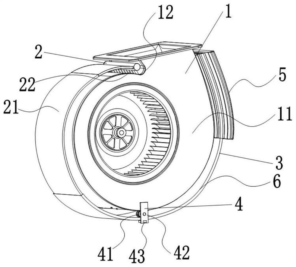
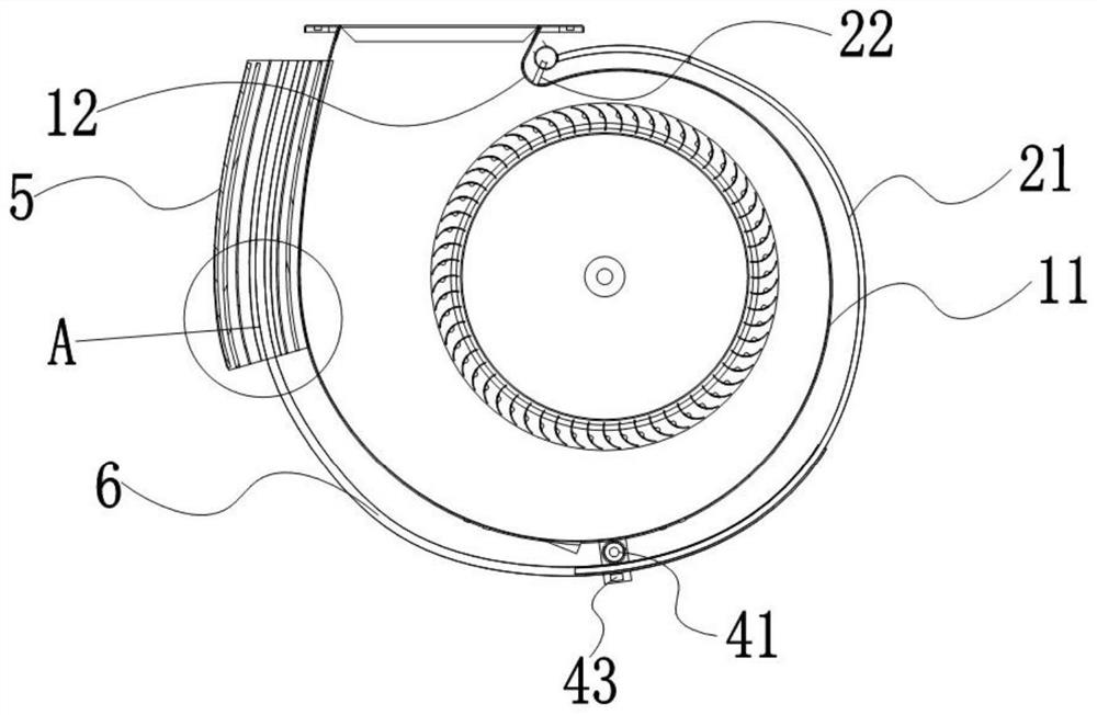
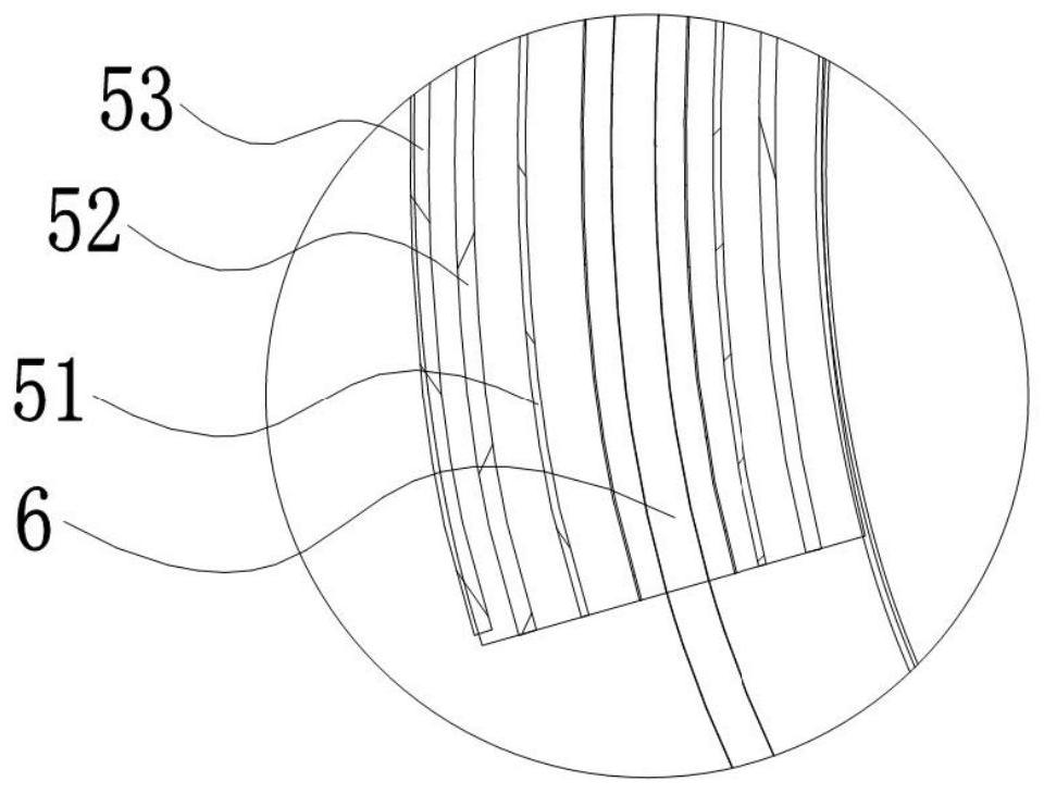
[0027] Such as Figures 1 to 3 As shown, this embodiment provides a noise reduction structure for a fan. The fan 1 has a volute 11, including a drainage device 2, a noise reduction device 3, a driving device 4 and a control device, wherein one end of the drainage device 2 is arranged on the volute 11. The volute tongue 12 is used to collect the noise at the position of the volute tongue 12, and the other end is extended along the circumferential direction of the volute 11, and the drainage device 2 and the noise reduction device 3 are movably connected together to jointly define a noise reduction channel, The drive device 4 is arranged on the outside of the volute 11, the noise reduction device 3 is slidably arranged on the volute 11 through the drive device 4, the drive device 4 is electrically connected with the control device, and the drive device 4 drives the noise reduction device 3 relative to the drainage device 2 Movement to achieve standing wave anechoicing at differe...

Embodiment 2

[0043] Such as Figures 1 to 3 As shown, this embodiment provides a range hood, including a fan 1, and the fan 1 is provided with the noise reduction structure as described in the first embodiment.

[0044] In this embodiment, the range hood is provided with a drainage device 2 at the position of the volute tongue 12 of the volute 11 to guide the impinging airflow so that it flows into the drainage device 2, thereby reducing the impact of the airflow on the position of the volute tongue 12. Impact, the noise entering the drainage device 2 continues to be transmitted in the direction of the noise reduction device 3, so that the noise reduction device 3 can reduce noise and silence the noise, and the noise reduction device 3 is driven by the drive device 4 to move relative to the drainage device 2 to adjust the noise reduction device. The length of the noise channel can be adjusted to achieve standing wave noise reduction at different frequencies. Adjusting the telescopic length...


PUM

PropertyMeasurementUnit
Thicknessaaaaaaaaaa
Thicknessaaaaaaaaaa
Thicknessaaaaaaaaaa

Abstract

The invention discloses a noise reduction structure of a fan and a range hood. The fan is provided with a volute and comprises a drainage device, a noise reduction device, a driving device and a control device, wherein one end of the drainage device is arranged on a volute tongue of the volute and used for collecting noise at the position of the volute tongue; the other end of the drainage deviceextends in the circumferential direction of the volute; the drainage device and the noise reduction device are movably connected together to jointly define a noise reduction channel; the driving device is arranged on the outer side of the volute; the noise reduction device is arranged on the volute in a sliding mode through the driving device; and the driving device is electrically connected withthe control device, and drives the noise reduction device to move relative to the drainage device so as to achieve standing wave noise elimination of different frequencies. The noise reduction structure is simple, and noise interference of the fan can be remarkably reduced, so that the noise reduction effect of the fan is further improved.

Description

technical field [0001] The invention relates to the technical field of kitchen appliances, in particular to a noise reduction structure of a fan and a range hood. Background technique [0002] In recent years, the hood market has been focusing on the concept of large air volume and large suction. With the improvement of people's quality of life, users pay more and more attention to the noise parameters of the range hood when purchasing range hoods. It can be said that the noise performance of the hood is The quality of products is a key factor in product competitiveness. [0003] In recent years, the domestic hood market has been mainly promoting the concept of large air volume and large suction. With the gradual increase of air volume, the noise generated by range hoods is also increasing. In the related art, when most of the range hoods are turned on during cooking, voices, telephones, doorbells and children’s voices cannot be heard, and even such strong noises will cause...

Claims


Application Information

Patent Timeline
IPC IPC(8): F04D29/66F24C15/20
CPCF04D29/663F04D29/664F04D29/665F04D29/667F24C15/20
Inventor 韩君庆潘叶江
Owner VATTI CORP LTD
Why Eureka
Eureka Blog
Learn More