
RCS measurement method based on three-dimensional sparse imaging

A technology of sparse imaging and measurement methods, which is applied in measurement devices, radio wave measurement systems, image data processing, etc. Effect

Inactive Publication Date: 2021-01-15
UNIV OF ELECTRONICS SCI & TECH OF CHINA
View PDF7 Cites 2 Cited by
  • Summary
  • Abstract
  • Description
  • Claims
  • Application Information

AI Technical Summary

Problems solved by technology

However, the 3D near-field scattering map obtained by the BP algorithm contains high target sidelobes and clutter, which affects the accuracy of RCS measurement

Method used


Image

  • RCS measurement method based on three-dimensional sparse imaging

Examples


Embodiment Construction

[0075] The present invention mainly adopts the method of simulation experiment for verification, and all steps and conclusions are verified correctly on the electromagnetic simulation software FEKO 2018 and the mathematical calculation software Matlab 2019b. The specific implementation steps are as follows:

[0076] Step 1. Initialize relevant parameters

[0077] Adopt the baseband signal form of the standard step frequency (SF) and the array three-dimensional SAR model, and initialize the following parameters: the propagation speed of light in the air is C=3×10 8 m / s;; SF signal center frequency is f 0 =9GHz; the step frequency number, recorded as n=1,2,...,161, the total number of frequency points is 161; the frequency step is Δf=12.5MHz; the composite bandwidth is B=2GHz; the array element number in the azimuth direction It is l=1,2,...,101; the orientation vector is d l =[0,1,0]; the array element spacing in the azimuth direction is Δdl=0.04m; the maximum aperture in th...


PUM


Abstract

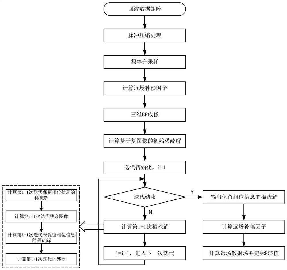
The invention discloses an RCS measurement method based on three-dimensional sparse imaging. The method comprises the following steps: acquiring an echo data matrix of a measured target area by usingan array three-dimensional SAR; completing preliminary signal processing by using pulse compression and frequency up-sampling technologies; utilizing a three-dimensional BP algorithm to obtain a three-dimensional complex image of target near-field scattering distribution; adopting a novel sparse imaging method based on a complex image to suppress target sidelobes and clutters; and finally obtaining an RCS directional diagram of the measured target by using a compensation factor and a calibration technology. Compared with a classic RCS measurement method based on images, the method is not influenced by sidelobes and clutters, can extract three-dimensional scattering characteristic distribution of the target, and has the advantages of high measurement precision, wide applicability and the like.

Description

technical field [0001] The invention belongs to the technical field of synthetic aperture radar, and in particular relates to the technical field of synthetic aperture radar (Synthetic Aperture Radar, SAR) sparse imaging and the technical field of radar cross-sectional area (Radar Cross Section) measurement. Background technique [0002] The radar cross section (RCS) is a physical quantity that characterizes the scattering ability of a target for radar electromagnetic waves. It is not only related to the geometric and physical parameters of the target, such as the shape, size, material and structure of the target, but also related to the parameters of the incident electromagnetic wave, such as polarization and frequency, and also related to the attitude angle of the target relative to the radar. RCS measurement technology refers to the technology of measuring the radar cross-sectional area of ​​the target by means of electromagnetic field theory and radar microwave imaging. ...

Claims


Application Information

Patent Timeline
Patent Type & Authority Applications(China)
IPC IPC(8): G01S13/90G01S7/41G01S7/292G01S7/28G06T17/00
CPCG01S13/9094G01S7/418G01S7/2813G01S7/292G06T17/00
Inventor 张晓玲王阳阳李阳陈益飞师君韦顺军
Owner UNIV OF ELECTRONICS SCI & TECH OF CHINA
Learn More