

Calibration method and arrangement structure of automatic driving environment perception sensor and vehicle
A technology of environment perception and automatic driving, which is applied to vehicle components, instruments, measuring devices, etc., can solve problems such as poor safety performance, a large number of manual operations, and low precision, so as to improve the degree of automation, reduce the number of sensors, and improve safety. Effect
- Summary
- Abstract
- Description
- Claims
- Application Information
AI Technical Summary
Problems solved by technology
Method used
Image

Examples
Embodiment 1
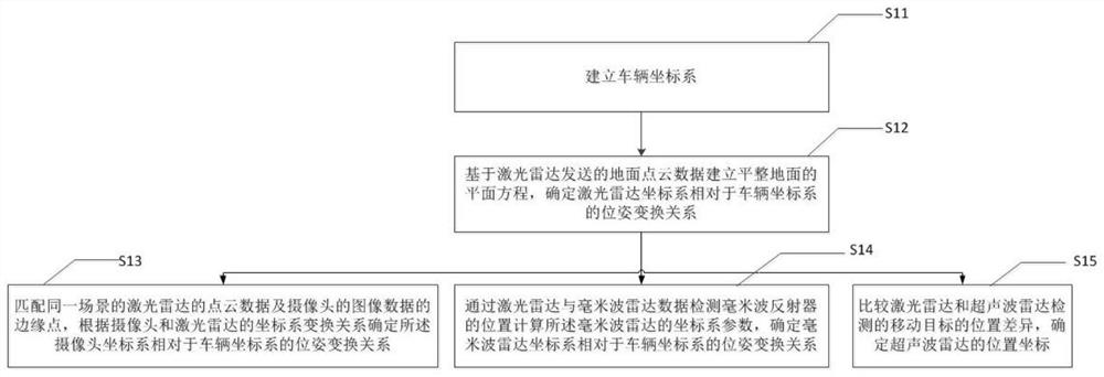
[0061] This embodiment provides a calibration method for an automatic driving environment perception sensor, such as figure 1 As shown, the calibration method includes:
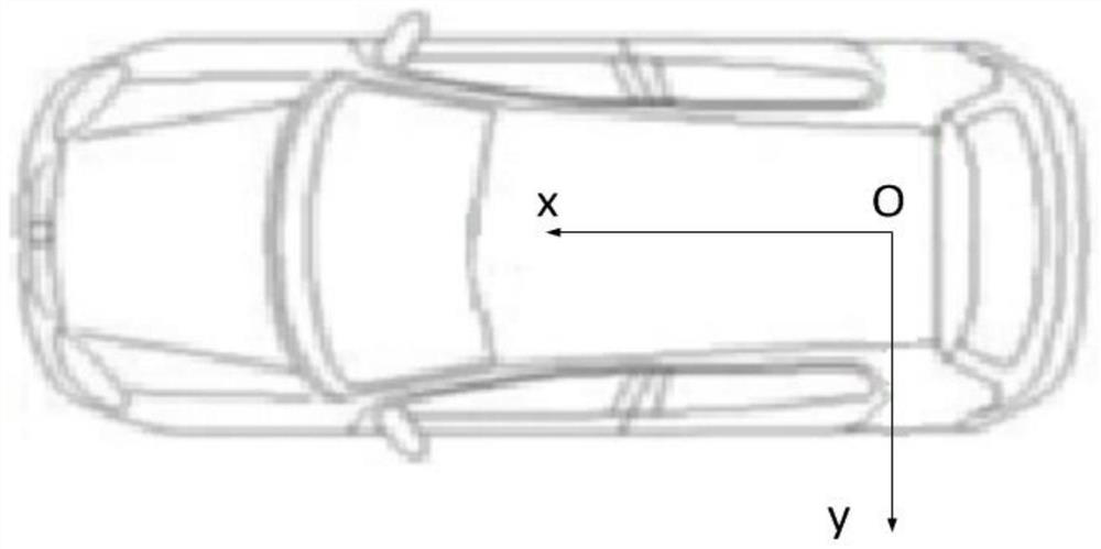
[0062] S11 establishes a vehicle coordinate system;
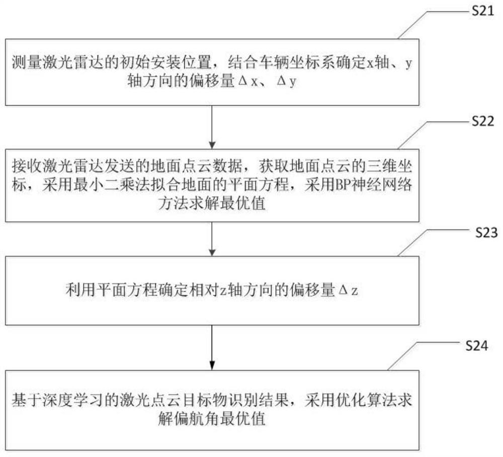
[0063] S12 establishes a plane equation for leveling the ground based on the ground point cloud data sent by the laser radar, and determines the pose transformation relationship of the laser radar coordinate system relative to the vehicle coordinate system;
[0064] S13 matching the edge points of the point cloud data of the laser radar and the image data of the camera in the same scene, and determining the pose transformation relationship of the camera coordinate system relative to the vehicle coordinate system according to the coordinate system transformation relationship of the camera and the laser radar;
[0065] S14 Detecting the position of the millimeter-wave reflector through the laser radar and the millimeter-wave radar data, calculating the coor...
Embodiment 2
[0099] An embodiment of the present invention provides an arrangement structure of environment perception sensors for automatic driving, such as Figure 8 As shown, it includes laser radar 11 arranged on the top of the vehicle; mid-range millimeter-wave radar 12, ultrasonic radar 13 and 360-degree surround-view camera 14 arranged staggered around the vehicle; long-distance millimeter-wave radar 15 arranged in front of the vehicle. The front camera 16 at the inner part of the front windshield of the vehicle, the harness connector of the laser radar 11, the long-distance millimeter wave radar 15, and the front camera 16 coincide with the vehicle central axis, and the middle distance millimeter wave radar 12 and ultrasonic radar 13 And 14 symmetrical settings of 360-degree surround view cameras.
[0100] This embodiment designs the arrangement of sensing sensors for a specific autonomous driving application scenario. According to the different sensing ranges of different sensors,...
Embodiment 3
[0127] Based on the same inventive concept, the embodiment of the present invention also provides a vehicle. Since the principle of the problem solved by the vehicle in this implementation is similar to the layout structure of the automatic driving environment perception sensor in the previous embodiment, the implementation of the vehicle in this embodiment can refer to the foregoing An embodiment of an arrangement structure of environment perception sensors for automatic driving, and repeated descriptions will not be repeated here.
[0128] An embodiment of the present invention provides a vehicle, and the vehicle includes an arrangement structure of environment perception sensors for automatic driving as described in any one of the above embodiments.
[0129] In this embodiment, a set of environment perception sensor configuration scheme suitable for automatic driving and an automatic calibration method for sensors are provided, and a new environment perception sensor arrange...
PUM
| Property | Measurement | Unit |
|---|---|---|
| Height | aaaaa | aaaaa |
Abstract
Description
Claims
Application Information