
Heat conduction paste coating method and device, computer equipment and readable storage medium

A thermally conductive paste and coating technology, which is applied to devices for applying liquid to surfaces, spraying devices, coatings, etc., can solve the problems of excessive thermally conductive paste, increased thermal conduction resistance, and decreased heat transfer effect.

Active Publication Date: 2021-01-22
广东芯聚能半导体有限公司
View PDF7 Cites 2 Cited by
  • Summary
  • Abstract
  • Description
  • Claims
  • Application Information

AI Technical Summary

Problems solved by technology

In the current IGBT chip production process, the chip bottom plate will be pre-bent in advance to offset the warping of the chip bottom plate caused by the mismatch of thermal expansion coefficients of different materials during the welding process, and the chip bottom plate warping produced on each IGBT chip There are certain differences
Printing or spraying is often used to evenly coat a layer of thermal paste on the contact surface of the chip base plate or the external heat sink, which will cause thermal paste in the center of the contact surface to appear during the process of tightening the IGBT chip and the external heat sink. If there is too much heat conduction paste and too little surrounding heat conduction paste, the heat conduction resistance will increase and the heat transfer effect will decrease.

Method used


Image

  • Heat conduction paste coating method and device, computer equipment and readable storage medium
  • Heat conduction paste coating method and device, computer equipment and readable storage medium

Examples


Embodiment Construction

[0042] In order to facilitate the understanding of the present invention, the present invention will be described more fully below with reference to the associated drawings. A preferred embodiment of the invention is shown in the drawings. However, the present invention can be embodied in many different forms and is not limited to the embodiments described herein. Rather, these embodiments are provided so that the disclosure of the present invention will be thorough and complete.

[0043] Unless otherwise defined, all technical and scientific terms used herein have the same meaning as commonly understood by one of ordinary skill in the technical field of the invention. The terms used herein in the description of the present invention are for the purpose of describing specific embodiments only, and are not intended to limit the present invention. As used herein, the term "and / or" includes any and all combinations of one or more of the associated listed items.

[0044] In the...


PUM


Abstract

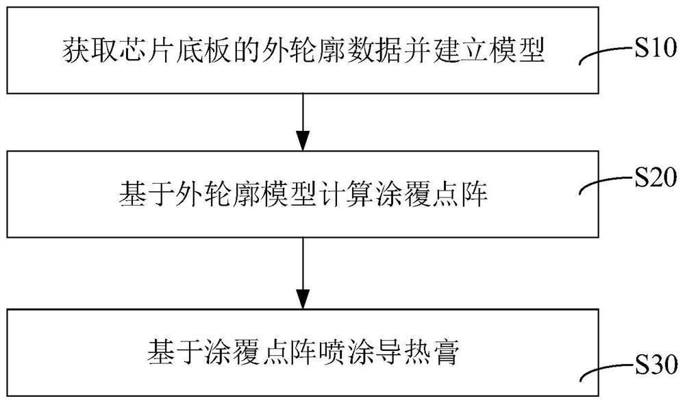
The invention relates to a heat conduction paste coating method which comprises the following steps of acquiring outer contour data of a chip bottom plate and establishing a model; calculating a coating dot matrix based on the outer contour model; and spraying heat conduction paste based on the coating dot matrix. According to the technical scheme, the spraying quantity of the heat-conducting paste can be compensated according to the warping degree of the chip bottom plate, dynamic adjustment can be realized according to different warping degrees of different chip bottom plates, the heat-conducting paste between the contact surfaces of the chip bottom plates and the external radiator is different in thickness, the heat conduction paste is properly compensated at the position where the chipbottom plate and the contact surface are not contacted, and the heat conduction paste can be directly conducted between the chip bottom plate and the contact surface at the position where the chip bottom plate and the contact surface can be contacted, so that the heat conduction paste between the chip bottom plate and the contact surface can just fill a gap between two planes without influencingthe tightly contacted positions of the two planes, the thermal resistance between the contact surfaces of the chip bottom plate and an external radiator is small, a heat transfer effect is good, and the optimization of the heat transfer effect is achieved.

Description

technical field [0001] The invention relates to the field of semiconductor production, in particular to a thermal paste coating method, device, computer equipment and readable storage medium. Background technique [0002] The heat dissipation of the existing high-power IGBT (Insulated Gate Bipolar Transistor, insulated gate bipolar transistor) chip is often realized through a large-area chip bottom plate and an external heat sink. The heat generated by the IGBT chip is transferred to the external heat sink through the chip bottom plate. Since there is a certain degree of roughness in the contact surface between the chip bottom plate and the external heat sink, the direct fit of the two rough planes will inevitably lead to the existence of voids. In the actual application process, it is necessary to apply an appropriate amount of thermal paste between the chip base plate and the contact surface of the external heat sink to fill the gap, reduce the thermal conduction resistanc...

Claims


Application Information

Patent Timeline
Patent Type & Authority Applications(China)
IPC IPC(8): B05D1/02B05B13/00B05B12/12
CPCB05D1/02B05B13/00B05B12/122
Inventor 闫鹏修朱贤龙
Owner 广东芯聚能半导体有限公司
Learn More