
Mechanical automation processing device for chain

A processing device and mechanical technology, which is applied to the attachment of shearing machines, feeding devices, shearing devices, etc., can solve the problems of chains that are difficult to reuse, chains that are difficult to handle, and chains that do not realize mechanical automation.

Active Publication Date: 2021-01-22
江苏松田电子科技有限公司
View PDF7 Cites 5 Cited by
  • Summary
  • Abstract
  • Description
  • Claims
  • Application Information

AI Technical Summary

Problems solved by technology

[0002] With the development of industrial technology, the development of modern machinery industry technology is becoming more and more perfect, so the mechanical transmission needs to use chain or belt transmission power, the belt transmission can be easily disassembled, but the belt and the roller are easy to slip when the belt is transmitted , then it is easy to generate relative motion between the two transmission wheels. If the linkage between the two transmission wheels needs to be maintained, a chain needs to be used for transmission. When the chain is in transmission, the two transmission wheels run synchronously, which is not easy Deviation occurs; the chain is a metal product, so the chain needs to be replaced after a long time of use, and the discarded chain is difficult to dispose of, and it is difficult to reuse the used chain, and the maintenance cost is even higher than buying a new chain , which requires the disposal of waste chains, but the waste disposal of chains has not been mechanically automated

Method used


Image

  • Mechanical automation processing device for chain
  • Mechanical automation processing device for chain
  • Mechanical automation processing device for chain

Examples


Embodiment Construction

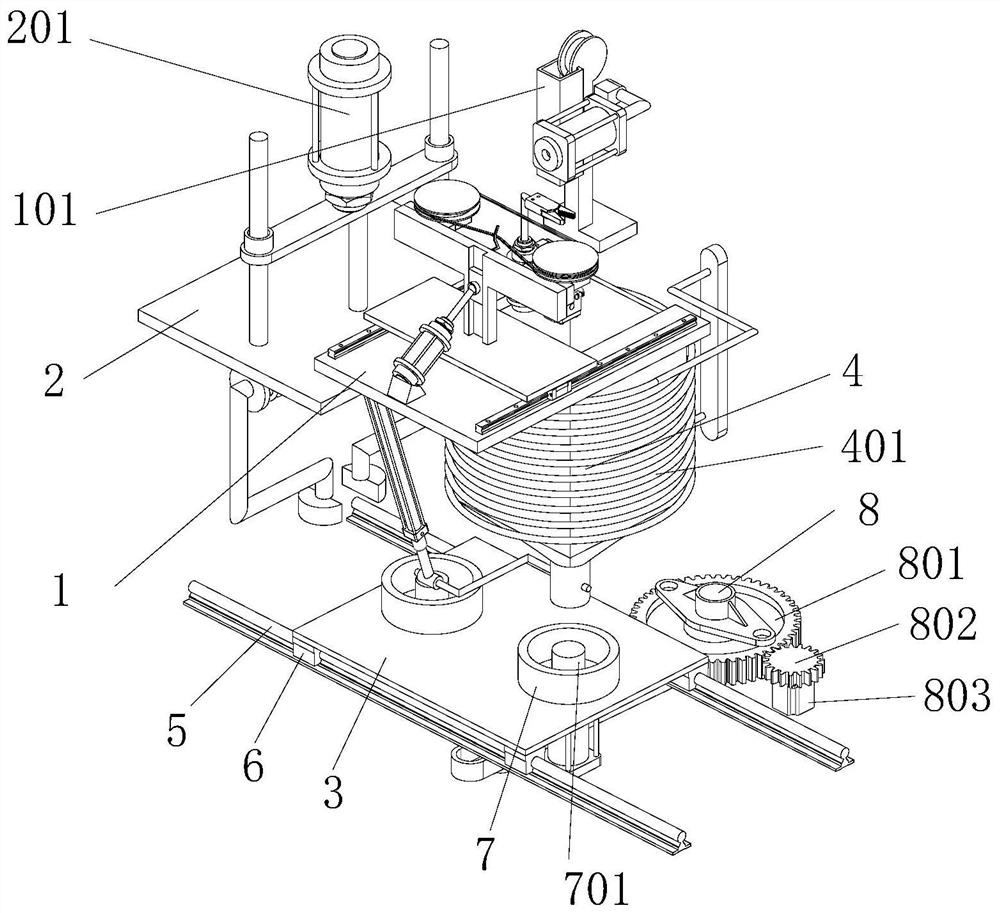
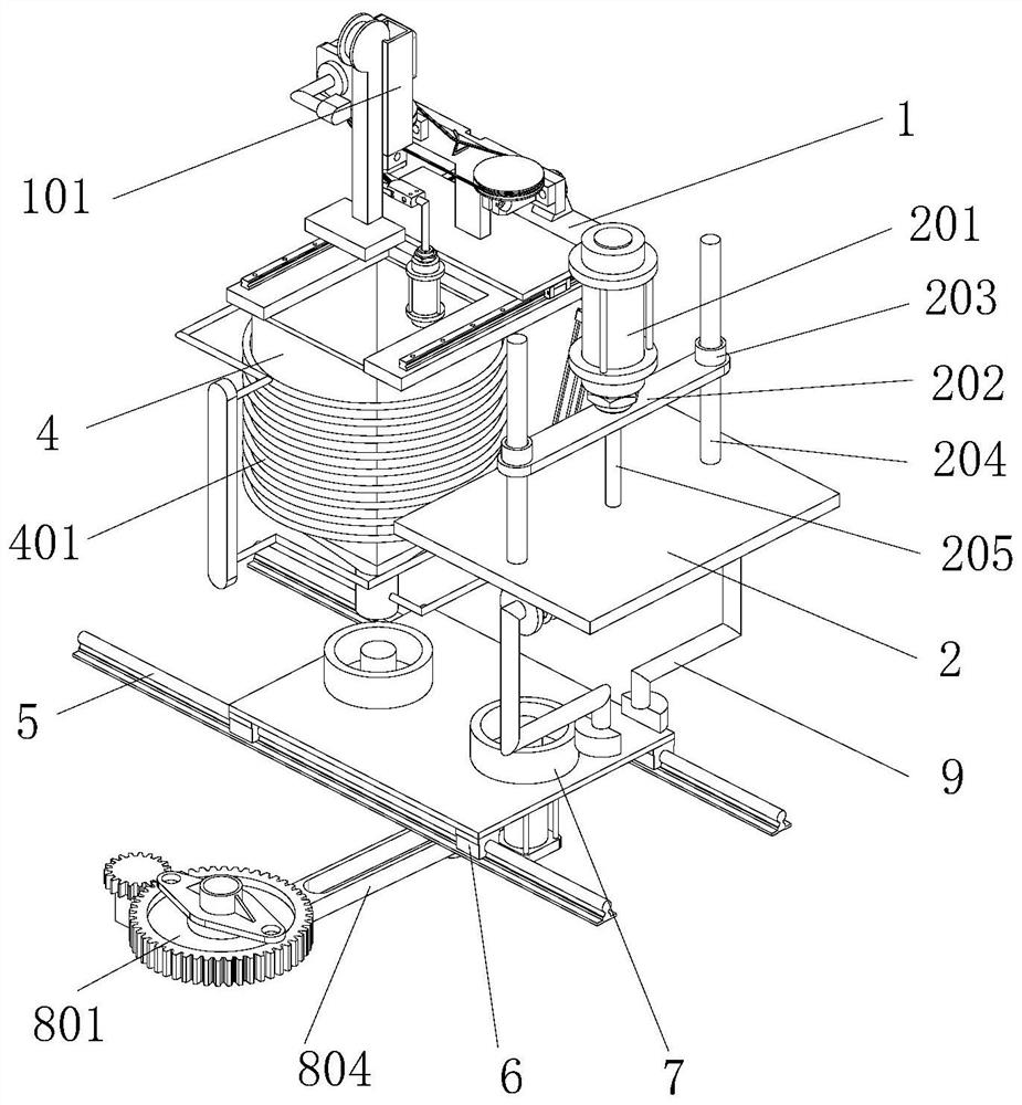
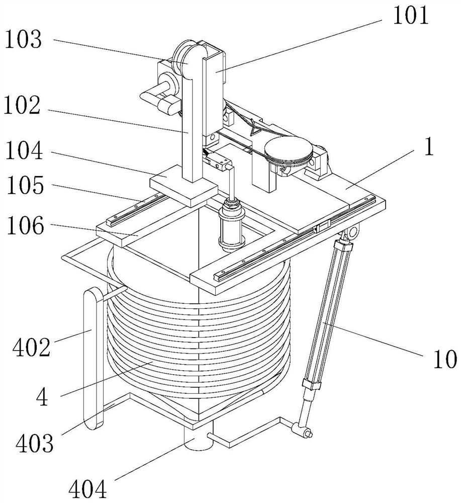
[0025] refer to Figures 1 to 8 The shown mechanical automatic processing device for a chain, for example, is a mechanical automatic processing device for waste chains, which includes a cutting table 1, and two pusher guide rails 105 are fixedly installed on the top of the cutting table 1, and each A sliding block 111 is installed on the propelling guide rail 105, and the sliding block 111 is slidably connected with the advancing guide rail 105. The tops of the two sliding blocks 111 are jointly fixedly installed with a sliding platform 112, and the top of the sliding platform 112 is fixedly installed with a vertical plate 11, and the vertical plate 11 Two shaft seats 14 are fixedly installed on one side of the shaft seat 14, and the two shaft seats 14 are respectively located at opposite ends of the vertical plate 11, and a cutting disc 16 is installed on the top of each shaft seat 14, and the cutting disc 16 and the shaft seat 14 are rotatably connected. , the two cutting di...


PUM


Abstract

The invention discloses a mechanical automation processing device of a chain, and belongs to the field of chain processing. The mechanical automation processing device comprises a shearing table, twopushing guide rails are fixedly arranged at the top end of the shearing table, sliding blocks are arranged on the pushing guide rails, the sliding blocks are in sliding connection with the pushing guide rails, and the top ends of the two sliding blocks are jointly and fixedly provided with a sliding table; a vertical plate is fixedly mounted at the top end of the sliding table, two shaft seats arefixedly mounted at one side of the vertical plate, cutting discs are mounted at the top ends of the shaft seats and rotationally connected with the shaft seats, the two cutting discs are connected through a fretsaw, one cutting disc is mounted at the output end of a cutting motor, and the output end of the cutting motor penetrates through one of the shaft seats to be fixedly connected with the cutting discs; and an elastic piece is fixedly installed at one side of the vertical plate, a ball head is installed at the output end of a pushing air cylinder, and a ball shell matched with the ball head is arranged at one side of a pushing sliding block. According to the mechanical automation processing device, the waste chain can be subjected to automatic mechanical treatment.

Description

technical field [0001] The invention relates to the field of chain processing, in particular to a mechanical automatic processing device for chains. Background technique [0002] With the development of industrial technology, the development of modern mechanical industry technology is becoming more and more perfect, so the mechanical transmission needs to use chain or belt transmission power, the belt transmission can be easily disassembled, but when the belt is transmitted, it is easy to slip between the belt and the roller , then it is easy to generate relative motion between the two transmission wheels. If the two transmission wheels need to be linked, this requires the use of a chain for transmission. When the chain is in transmission, the two transmission wheels run synchronously, which is not easy Deviation occurs; the chain is a metal product, so the chain needs to be replaced after a long time of use, and the discarded chain is difficult to dispose of, and it is diff...

Claims


Application Information

Patent Timeline
IPC IPC(8): B23D19/00B23D33/02B23Q5/28B23Q11/10
CPCB23D19/00B23D33/02B23Q5/28B23Q11/10
Inventor 沈古震
Owner 江苏松田电子科技有限公司
Learn More