Eureka AIR delivers breakthrough ideas for toughest innovation challenges, trusted by R&D personnel around the world.

Workbench for machining of welding robot and using method of workbench

A welding robot and workbench technology, applied to chemical instruments and methods, cleaning methods using gas flow, welding equipment, etc., can solve the problems of decreased welding effect, lack of vertical angle adjustment, and reduced work efficiency to meet the requirements of Requirements for welding working angle, avoiding the impact on health, and improving work efficiency

Inactive Publication Date: 2021-01-22
NANJING HANXIYUE AUTOMATION TECH CO LTD
View PDF0 Cites 1 Cited by
  • Summary
  • Abstract
  • Description
  • Claims
  • Application Information

AI Technical Summary

Problems solved by technology

[0004] The main purpose of the present invention is to provide a welding robot processing workbench, which can effectively solve the problem in the background technology that it does not have a rotation function. When welding, the welding workpiece cannot be rotated in the horizontal direction, so that the workpiece needs to be taken out for secondary installation. It increases the complexity of the work and reduces the work efficiency; secondly, it does not have the function of vertical angle adjustment, and the simple horizontal sliding function cannot meet the angle requirements of the welding robot for the welding workpiece, which reduces the welding effect and further increases the work. Time-consuming; in addition, it does not have the function of welding fume treatment, and welding fume will be generated during welding work, and if the welding fume is not treated, it will affect the health of the staff, and the use effect is poor Technical problems

Method used


Image

  • Workbench for machining of welding robot and using method of workbench
  • Workbench for machining of welding robot and using method of workbench
  • Workbench for machining of welding robot and using method of workbench

Examples


Embodiment Construction

[0031] In order to make the technical means, creative features, goals and effects achieved by the present invention easy to understand, the present invention will be further described below in conjunction with specific embodiments.

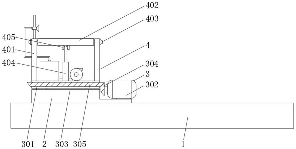
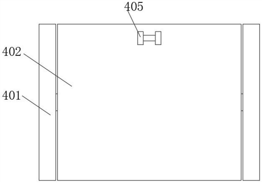
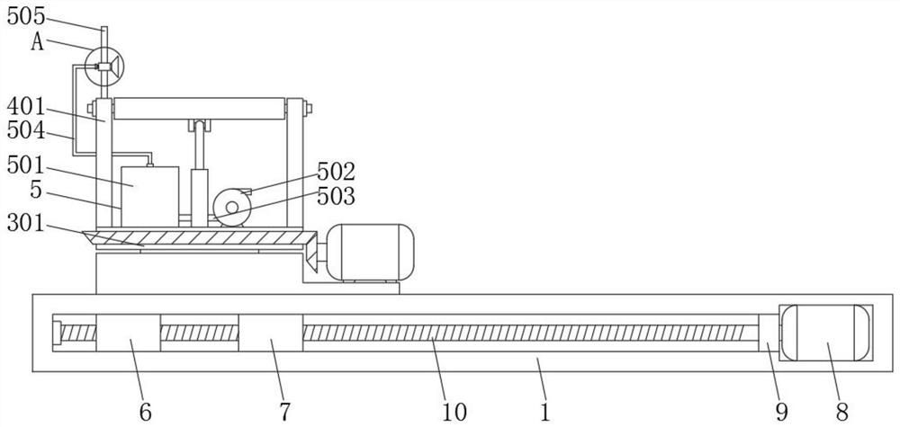
[0032] Such as Figure 1-6 As shown, a welding robot processing workbench includes a support platform 1, a sliding seat 2 is slidably installed on the upper part of the support platform 1, and a rotating mechanism 3 is provided on the upper part of the sliding seat 2. The rotating mechanism 3 includes a rotating platform 301, a rotating Motor 302, rotating shaft 303, active bevel gear 304 and driven bevel gear 305, and the top of rotary table 301 is provided with angle adjustment mechanism 4, and angle adjustment mechanism 4 includes support plate 401, work table 402, connecting shaft 403, cylinder 404 and The shaft seat 405, the welding fume purification mechanism 5 is provided between the upper part of the rotary table 301 and the support plate ...


PUM


Abstract

The invention discloses a workbench for machining of a welding robot and a using method of the workbench.The workbench comprises a supporting table, a sliding base is slidably installed on the upper portion of the supporting table, a rotating mechanism is arranged on the upper portion of the sliding base, and the rotating mechanism comprises a rotating table, a rotating motor, a rotating shaft, adriving bevel gear and a driven bevel gear. An angle adjusting mechanism is arranged on the upper portion of the rotating table and comprises a supporting plate, a workpiece table, a connecting shaft,an air cylinder and a shaft base. According to the workbench for machining of the welding robot, the rotating function can be achieved, a welding workpiece can be rotated in the horizontal direction,the working efficiency is improved, in addition, the function of adjusting the angle in the vertical direction is achieved, the requirement of the welding robot for the welding working angle can be met, the welding effect is improved, and the working time consumption is reduced; and in addition, the welding fume generated during welding can be treated, the influence of direct emission of the welding fume on the body health of workers is avoided, and the use effect is better.

Description

technical field [0001] The invention relates to the field of workbenches, in particular to a workbench for welding robot processing, and more particularly to a workbench for welding robot processing and a method for using the same. Background technique [0002] Welding robot is an industrial robot used for welding metal workpieces. It can be controlled by software programs to complete very precise welding work. During welding, the workpieces to be welded need to be fixed on the workbench, so it is necessary to use Working table for welding robot processing; [0003] However, the existing workbenches for welding robots have certain deficiencies in use and need to be improved. First, they do not have a rotation function. When welding, they cannot rotate the welding workpiece in the horizontal direction, so that the workpiece needs to be taken out for a second time. Installation increases the complexity of the work and reduces work efficiency; secondly, it does not have the fu...

Claims


Application Information

Patent Timeline
Patent Type & Authority Applications(China)
IPC IPC(8): B23K37/02B23K37/00B08B5/04
CPCB23K37/0252B23K37/00B08B5/04
Inventor 李定国潘晓平
Owner NANJING HANXIYUE AUTOMATION TECH CO LTD
Why Eureka
Eureka Blog
Learn More