Combined machining workbench

A machining and workbench technology, applied in the field of combined machining workbenches, can solve the problems that the workbench cannot be raised and lowered to adjust the height, and the stability of the roller support is poor, so as to reduce shaking, improve work efficiency, and reduce labor intensity.

Inactive Publication Date: 2021-01-22
深圳利朋技术研发有限公司
View PDF0 Cites 4 Cited by
  • Summary
  • Abstract
  • Description
  • Claims
  • Application Information

AI Technical Summary

Problems solved by technology

[0004] The purpose of the present invention is to solve the problems in the prior art that the workbench cannot be lifted up and down to adjust the height and the support stability is poor by using rollers, and a combined machining workbench is proposed

Method used


Image

  • Combined machining workbench
  • Combined machining workbench
  • Combined machining workbench

Examples


Embodiment 1

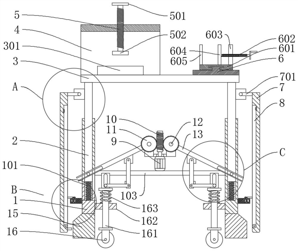
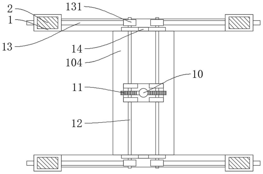
[0032] refer to Figure 1-7, a combined mechanical processing workbench, including a support rod 1, a motor 9, a connecting rod 12, a pressing mechanism and a clamping mechanism. There is a first slide bar 2, the first slide bar 2 is fixedly connected with a table top 3, both the pressing mechanism and the clamping mechanism are fixedly connected with the table top 3, the output end of the motor 9 is fixedly connected with a threaded rod 10, and the connecting rod 12 is fixed A gear 11 and a second rotary sleeve 131 are connected, the gear 11 is meshed with the threaded rod 10, the second rotary sleeve 131 is fixedly connected with a rocker 13, the rocker 13 is slidably connected with the first slide bar 2, and the rocker 13 is fixed Connected with card base 132, the card base 132 is rotatably connected with the first swing rod 18, and the end of the first swing rod 18 away from the card base 132 is rotatably connected with the second swing rod 19, and the second swing rod 19 ...

Embodiment 2

[0044] refer to Figure 1-7 , a combined mechanical processing workbench, including a support rod 1, a motor 9, a connecting rod 12, a pressing mechanism and a clamping mechanism. There is a first slide bar 2, the first slide bar 2 is fixedly connected with a table top 3, both the pressing mechanism and the clamping mechanism are fixedly connected with the table top 3, the output end of the motor 9 is fixedly connected with a threaded rod 10, and the connecting rod 12 is fixed A gear 11 and a second rotary sleeve 131 are connected, the gear 11 is meshed with the threaded rod 10, the second rotary sleeve 131 is fixedly connected with a rocker 13, the rocker 13 is slidably connected with the first slide bar 2, and the rocker 13 is fixed Connected with card base 132, the card base 132 is rotatably connected with the first swing rod 18, and the end of the first swing rod 18 away from the card base 132 is rotatably connected with the second swing rod 19, and the second swing rod 19...

Embodiment 3

[0056] refer to Figure 1-7 , a combined mechanical processing workbench, including a support rod 1, a motor 9, a connecting rod 12, a pressing mechanism and a clamping mechanism. There is a first slide bar 2, the first slide bar 2 is fixedly connected with a table top 3, both the pressing mechanism and the clamping mechanism are fixedly connected with the table top 3, the output end of the motor 9 is fixedly connected with a threaded rod 10, and the connecting rod 12 is fixed A gear 11 and a second rotary sleeve 131 are connected, the gear 11 is meshed with the threaded rod 10, the second rotary sleeve 131 is fixedly connected with a rocker 13, the rocker 13 is slidably connected with the first slide bar 2, and the rocker 13 is fixed Connected with card base 132, the card base 132 is rotatably connected with the first swing rod 18, and the end of the first swing rod 18 away from the card base 132 is rotatably connected with the second swing rod 19, and the second swing rod 19...


PUM


Abstract

The invention discloses a combined machining workbench, and belongs to the field of machining workbenches. The combined machining workbench comprises a supporting rod, a motor, a connecting rod, a pressing mechanism and a clamping mechanism. A first sliding groove is formed in the supporting rod, a first sliding rod is connected into the first sliding groove in a sliding manner, a table top is fixedly connected to the first sliding rod, and the pressing mechanism and the clamping mechanism are both fixedly connected to the table top; and a threaded rod is fixedly connected to the output end ofthe motor, a gear and a second rotating sleeve are fixedly connected to the connecting rod, the gear is connected with the threaded rod in an engaged manner, and a rocker is fixedly connected to thesecond rotating sleeve. The combined machining workbench is easy to use and convenient to lift, the lifting function of the workbench is added, the labor intensity of a user is reduced, and the use efficiency is improved; and meanwhile, idler wheels are driven to move up and down through lifting, so that the balance of the stability and the moving portability of the workbench is achieved.

Description

technical field [0001] The invention relates to the technical field of machining workbenches, in particular to a combined machining workbench. Background technique [0002] Machining refers to the process of changing the shape or performance of a workpiece through a mechanical device; it can be divided into cutting processing and pressure processing according to the difference in processing methods. The production process of a machine refers to the entire process of making a product from raw materials (or semi-finished products). For machine production, it includes transportation and storage of raw materials, production preparation, blank manufacturing, processing and heat treatment of parts, product assembly, debugging, painting and packaging, etc. In mechanical processing, the workbench is suitable for molds and fitters , detection, maintenance, assembly and other different applications, with good corrosion resistance, dirt resistance, impact resistance and strong load-be...

Claims


Application Information

Patent Timeline
Patent Type & Authority Applications(China)
IPC IPC(8): B25H1/16B25H1/14
CPCB25H1/14B25H1/16
Inventor 不公告发明人
Owner 深圳利朋技术研发有限公司
Why Eureka
Try Eureka