Air flow control device, fan blade comprising same and wind generating set

A control device and air flow technology, applied in the fields of wind turbine blades, air flow control devices, and wind turbines, can solve the problems of boundary layer flow separation of wind power blades, improve anti-separation ability, strengthen energy mixing, and increase internal energy. Effect

Active Publication Date: 2021-01-22
SHANGHAI ELECTRIC WIND POWER GRP CO LTD
View PDF13 Cites 0 Cited by
  • Summary
  • Abstract
  • Description
  • Claims
  • Application Information

AI Technical Summary

Problems solved by technology

[0004] The technical problem to be solved by the present invention is to overcome the defect that the boundary layer flow separation phenomenon of the wind power blades will occur in the prior art when the wind power generating set is running, and to provide an air flow control device and the fan blades and wind generating set containing it.

Method used


Image

  • Air flow control device, fan blade comprising same and wind generating set
  • Air flow control device, fan blade comprising same and wind generating set
  • Air flow control device, fan blade comprising same and wind generating set

Examples


Embodiment Construction

[0079] In the following, the present invention will be more clearly and completely described by means of an embodiment in conjunction with the accompanying drawings, but the present invention is not limited to the scope of the embodiment.

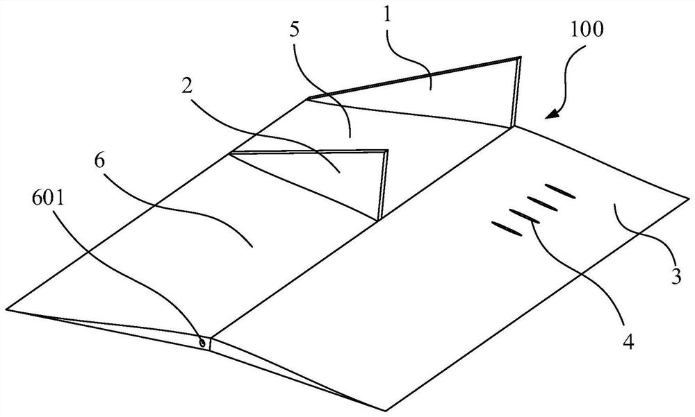
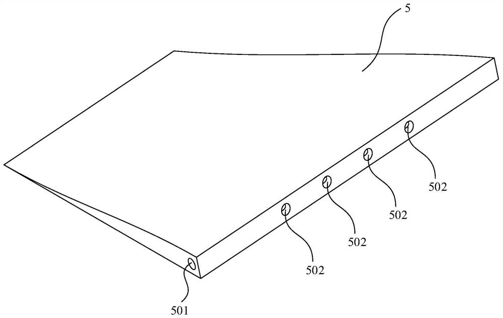
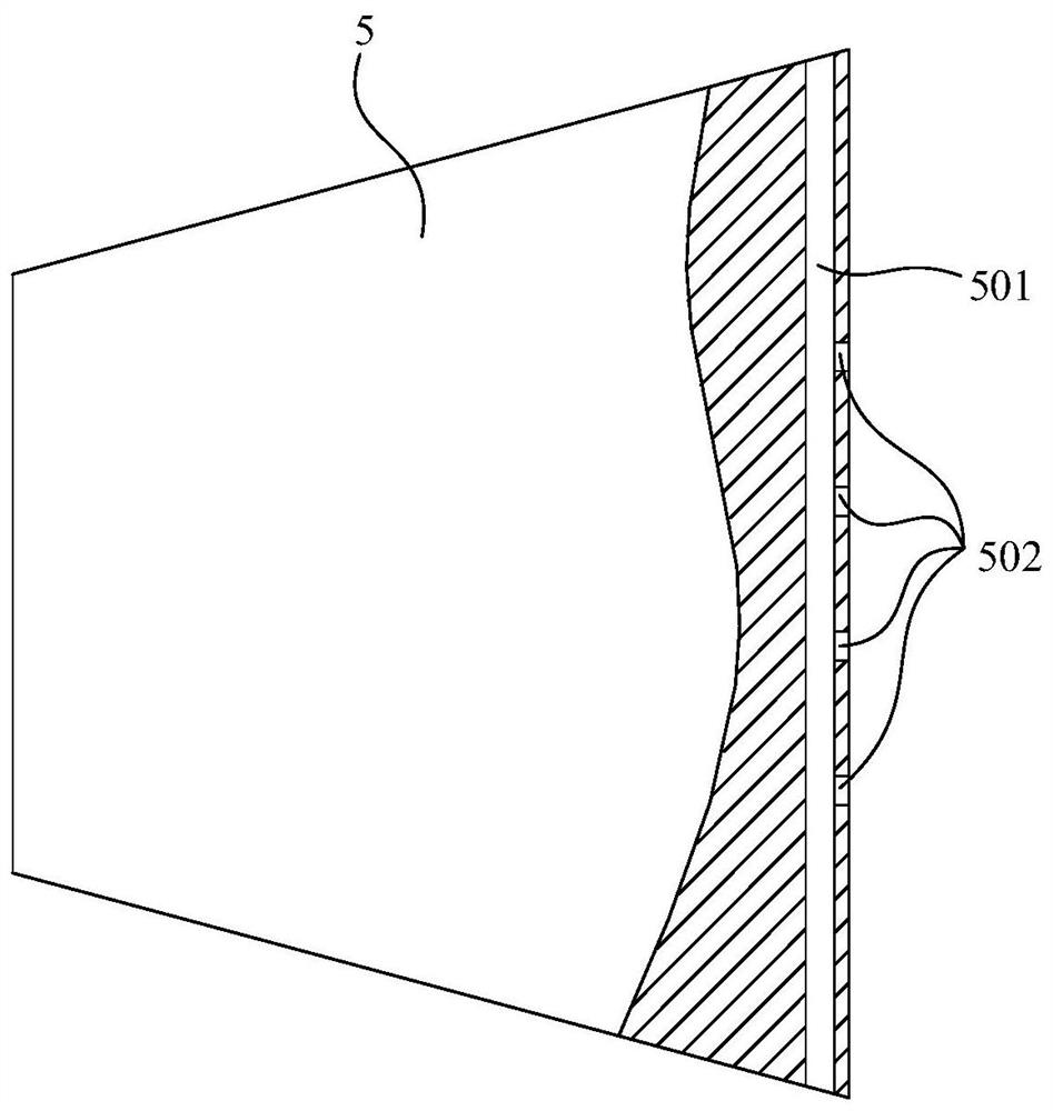
[0080] Such as Figure 1-9 As shown, it is an air flow control device in this embodiment, and the air flow control device includes at least one control unit 100, wherein the control unit 100 includes two opposite vertical plates and an exhaust assembly, between the two vertical plates The distance from the front to the rear gradually increases, and the exhaust assembly has an exhaust hole 4 capable of injecting gas, and the exhaust hole 4 is located in the rear area between the two vertical plates. Wherein, when the exhaust hole 4 is set, the opening of the exhaust hole 4 faces the air flow direction passing through the area between the two vertical plates, so that the airflow direction of the exhaust hole 4 ejected gas and the incoming flo...


PUM


Abstract

The invention discloses an air flow control device, a fan blade comprising the same and a wind generating set. The air flow control device comprises at least one control unit, the control unit comprises two oppositely arranged vertical plates and an exhaust assembly, the distance between the two vertical plates is gradually increased from front to back, the exhaust assembly is provided with an exhaust hole capable of spraying gas, and the exhaust hole is formed in the rear side area between the two vertical plates. According to the air flow control device, air flow flowing through the surfaceof a fan blade flows through the area between the two vertical plates to generate vortex, external energy of a boundary layer of the fan blade is mixed into the boundary layer, internal energy of theboundary layer is increased, the vortex center of the vortex is driven to move downwards through the air flow sprayed out of the exhaust hole of the exhaust assembly, thus energy mixing of the boundary layer is enhanced, internal energy of the boundary layer is further increased, and separation resistance of the boundary layer is improved.

Description

technical field [0001] The invention relates to the field of wind power generation, in particular to an air flow control device, a fan blade and a wind power generating set including the device. Background technique [0002] When the wind turbine is running, if the angle of attack of the blade is too large, the blade will have boundary layer flow separation phenomenon, which is called blade stall. The flow separation will cause the lift force of the blade to drop rapidly and the resistance to rise rapidly, resulting in the decline of the aerodynamic performance of the blade and the power generation capacity. The loss was serious. With the increasing size of wind power blades, the requirements for the blade structure are getting higher and higher, and the airfoil with large thickness and blunt trailing edge has become the first choice for the airfoil at the root end of the blade. During the operation of wind turbines, the boundary layer flow separation in the root region of ...

Claims


Application Information

Patent Timeline
Patent Type & Authority Applications(China)
IPC IPC(8): F03D7/04F03D1/06
CPCF03D7/04F03D7/022F03D1/0675Y02E10/72
Inventor 赵越艾国远李海涛赵大文
Owner SHANGHAI ELECTRIC WIND POWER GRP CO LTD
Why Eureka
Try Eureka