
Intelligent laser device for fire escape

A laser and intelligent technology, applied in display devices, instruments, supporting machines, etc., can solve the problems of inability to provide escape instructions, inability to timely command escape and evacuation, and panic among crowds, so as to avoid crowd panic.

Inactive Publication Date: 2021-01-22
沈阳泽天科技有限公司
View PDF0 Cites 2 Cited by
  • Summary
  • Abstract
  • Description
  • Claims
  • Application Information

AI Technical Summary

Problems solved by technology

[0002] Existing fire escape devices have floor stickers, signs at the entrances and exits, and landmark safety passages, which will be blocked by people walking on them. The direction of escape is fixed. If the direction pointed is exactly where the disaster is located, people will gather in the wrong direction and cause more damage. The fire is accompanied by thick smoke, which obscures the existing indicating device and loses its indicating function. The safety signs are powered by alternating current, so there are potential electrical safety hazards. The fire broadcast cannot be used for intercom, and the on-site video cannot be seen, resulting in the inability to command the evacuation in time and delay the best time to escape.
[0003] Because there are many problems in the existing fire escape devices, the indication function of fire exits and safety doors is reduced, it is difficult to plan the correct escape route, and the crowd is in a panic. Because of the urgent need for an intelligent laser device for fire escape

Method used


Image

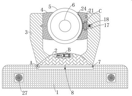
  • Intelligent laser device for fire escape
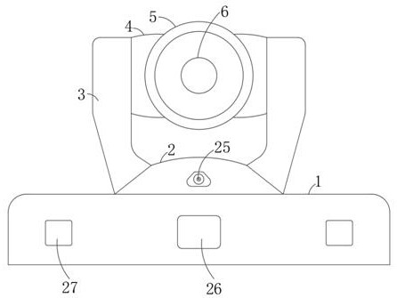
  • Intelligent laser device for fire escape
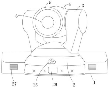
  • Intelligent laser device for fire escape

Examples


Embodiment Construction

[0023] The following will clearly and completely describe the technical solutions in the embodiments of the present invention with reference to the accompanying drawings in the embodiments of the present invention. Obviously, the described embodiments are only some, not all, embodiments of the present invention.

[0024] In describing the present invention, it should be understood that the terms "upper", "lower", "front", "rear", "left", "right", "top", "bottom", "inner", " The orientation or positional relationship indicated by "outside", etc. is based on the orientation or positional relationship shown in the drawings, and is only for the convenience of describing the present invention and simplifying the description, rather than indicating or implying that the referred device or element must have a specific orientation, so as to Specific orientation configurations and operations, therefore, are not to be construed as limitations on the invention.

[0025] refer to Figure ...


PUM


Abstract

The invention discloses an intelligent laser device for fire escape. The intelligent laser device comprises a pan tilt, wherein a high fastball is arranged above the pan tilt; the same adjustment assembly is arranged on the pan tilt and the high fastball; a self-cooling mechanism is arranged in the high fastball; built-in patterns including fire channels, indicating arrows, stairwells, safe escapedoors and the like can be scanned through an oscillating mirror which is arranged on a laser, and meanwhile, a correct escape route is planned according to real-time disaster in a fire scene; the direction can be configured in advance and also can be configured in real time, and because of an integrated wide-angle fisheye lens IP intercom system, real-time visible intercom with the far-end fire department can be realized, convenience is provided for fire organizations to know the disaster scene in time, and the fire organization can command persons to escape in real time so as to avoid hurryand confusion; and meanwhile, the intelligent laser device also can be used for inspection and visit of fire fighting as usual, and also can realize horizontal rotation of angels of the high-speed pantilt; and by using centrifugal force produced by rotation as driving force, automatic cooling and heat radiation treatment of the high fastball is realized, and dust particles of dense smoke attachedwith the lens surface of a laser lens also can be removed.

Description

technical field [0001] The invention relates to the technical field of fire escape equipment, in particular to an intelligent laser device for fire escape. Background technique [0002] Existing fire escape devices have floor stickers, signs at the entrances and exits, and landmark safety passages, which will be blocked by people walking on them. The direction of escape is fixed. If the direction pointed is exactly where the disaster is located, people will gather in the wrong direction and cause more damage. The fire is accompanied by thick smoke, which obscures the existing indicating device and loses its indicating function. The safety signs are powered by alternating current, and there are potential electrical safety hazards in themselves. The fire broadcast cannot be used for intercom, and the on-site video cannot be seen, which makes it impossible to command the evacuation in time, and delays the best time to escape. [0003] Because there are many problems in the exi...

Claims


Application Information

Patent Timeline
Patent Type & Authority Applications(China)
IPC IPC(8): F16M11/04F16M11/14F16M11/18B08B5/02B08B11/00G09F19/12H04N7/14H05K7/20
CPCB08B5/02B08B11/00F16M11/04F16M11/14F16M11/18G09F19/12H04N7/142H05K7/20
Inventor 李龙
Owner 沈阳泽天科技有限公司
Learn More