Testing device for gas-detonation-driven ultra-high-speed emission

A test device and ultra-high-speed technology, which is applied to the test of ammunition, weapon accessories, ammunition, etc., can solve the problems of the projectile's horizontal direction is not perfect uniform motion, not enough to completely analyze the experimental process, unable to analyze the test failure and other problems. The effect of easy system maintenance, rich experimental data and accurate time

Active Publication Date: 2021-01-22
INST OF MECHANICS - CHINESE ACAD OF SCI
View PDF5 Cites 2 Cited by
  • Summary
  • Abstract
  • Description
  • Claims
  • Application Information

AI Technical Summary

Problems solved by technology

[0007] 1. Low sensitivity, often does not trigger
[0008] The speed of the projectile is very fast, and the change in light intensity caused by the rapid flight is too small, so that the detection system cannot detect it and cause no trigger, and cannot take pictures normally
[0009] 2. There are many false triggers
[0012] 3. Insufficient data for analysis after the test
[0013] The signal collected by the acquisition card is not enough to fully analyze the experiment process, and the reason for the experiment failure cannot be analyzed from the detector signal when the experiment fails
When the experiment is normal, the accuracy of the measurement cannot be improved from the signal analysis
[0014] To sum up, the original system in the prior art only calculates the velocity. When the vacuum degree is not high enough or the blasting gas enters the projectile flight space, the projectile does not move perfectly at a uniform speed in the horizontal direction.

Method used


Image

  • Testing device for gas-detonation-driven ultra-high-speed emission
  • Testing device for gas-detonation-driven ultra-high-speed emission
  • Testing device for gas-detonation-driven ultra-high-speed emission

Examples


Embodiment 1

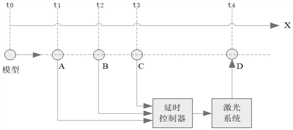
[0044] Such as figure 2 As shown, a gas detonation-driven ultra-high-speed launch test device includes a model and a target room measurement section at a certain distance from the model. A window and B window are respectively arranged at a certain distance in the target room measurement section. Four observation windows, window C, window D, window A, window B, and window C are respectively connected to the delay controller, and a laser system and a camera are installed at the position of window D, and the projectiles sequentially pass from the detection point A window, B window, C window When the window passes, the flight speed is calculated by calculating the flight time between adjacent detection windows, and then the delay time is calculated. The delay time is output by the delay controller to control the laser system to flash, and the projectile passes through the camera. Schlieren image of the D window.

[0045] Such as figure 2 As shown, if the three windows are trig...

Embodiment 2

[0056] On the basis of the embodiment, different from embodiment 1, a model of a gas detonation-driven ultra-high-speed emission test device adopts a two-stage structure design. The model includes a camera system for imaging, a measurement and control system for controlling flashes, and a processing and collection systems,

[0057] The photographing system includes a laser light source, a horizontal schlieren instrument, a vertical schlieren instrument, a collimating mirror, a reference flange, a window glass, a camera, and a camera controller. The straight mirror is equipped with a horizontal schlieren instrument and a vertical schlieren instrument, the laser light source is connected to the horizontal schlieren instrument through a horizontal optical fiber, and the laser light source is connected to the vertical schlieren instrument through a vertical optical fiber;

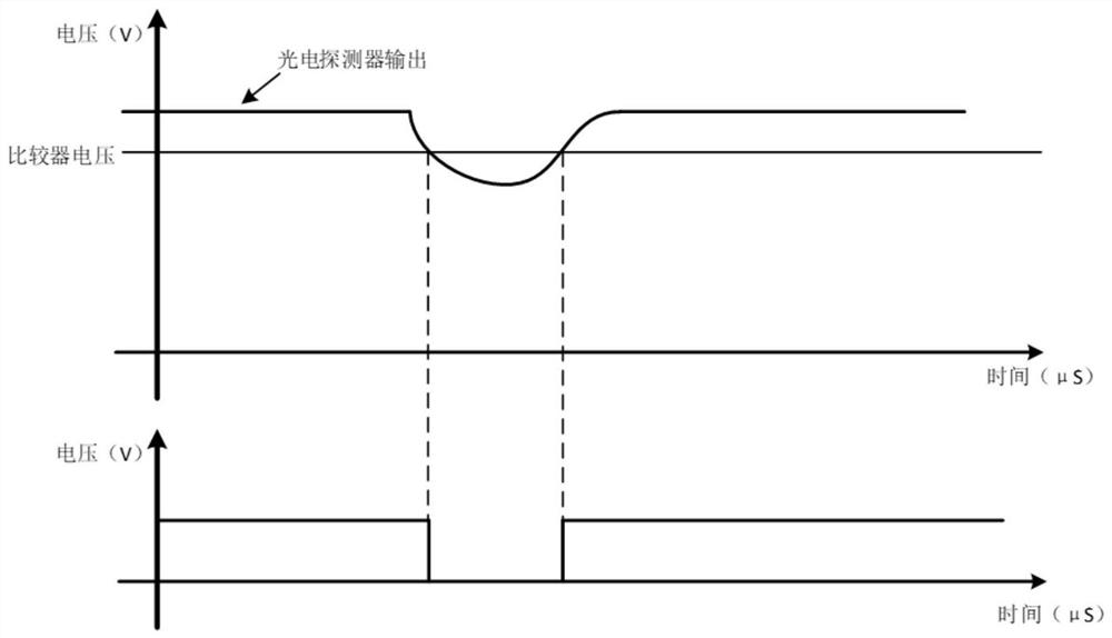
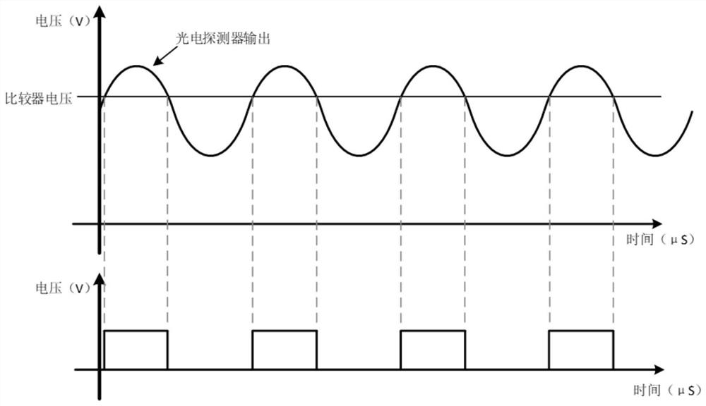
[0058] The measurement and control system for controlling the flash includes a laser light source, a photode...


PUM


Abstract

The invention discloses a testing device for gas-detonation-driven ultra-high-speed emission. The testing device for gas-detonation-driven ultra-high-speed emission comprises a model and a target chamber measuring section at a position a certain distance away from the model, wherein four observation windows A, B, C and D are sequentially formed in the target chamber measuring section at certain intervals separately; the window A, the window B and the window C are connected with a delay controller separately; a laser system and a camera are arranged at the position of the window D; a projectilepasses through the window A, the window B and the window C of a detection point in sequence, a flight speed is calculated by calculating the flight time between the adjacent detection windows, then the time needing to be delayed is calculated, the delay controller outputs the delay time to control the laser system to flash, and a schlieren image of the projectile passing through the window D is captured through the camera. Higher stability is achieved; higher sensitivity is achieved, and a non-triggering phenomenon is avoided; experimental data is richer, and analysis of experimenters is facilitated; and the time can be corrected manually and accurately.

Description

technical field [0001] The invention belongs to the technical field of ultra-high-speed projectile / model test equipment, and in particular relates to a test device for ultra-high-speed launch driven by gas detonation. Background technique [0002] The gas detonation-driven ultra-high-speed launch test device is used to measure the flight model flow field, attitude and velocity measurement. It is necessary to establish a multi-set shadow (schlieren) camera system on the basis of multiple sets of shadow (schlieren) camera systems in the target room measurement section and configure the model detection and reference system. The measurement and control system is used to obtain test data and pictures. [0003] The method usually adopted in the prior art is the principle of a single observation window, by calculating the distance of the projectile to point AB / the flight time of point AB, the flight speed is calculated, and then the time that needs to be delayed is calculated. But...

Claims


Application Information

Patent Timeline
Patent Type & Authority Applications(China)
IPC IPC(8): F42B35/00
CPCF42B35/00
Inventor 魏炳忱汪球赵伟
Owner INST OF MECHANICS - CHINESE ACAD OF SCI
Why Eureka
Try Eureka